Signal
General
A signal in TARGET 3001! is the electrical connection between two or more terminals (pins). In the schematic we speak of a signal. Its counterpart in the layout we would call a track.
You can reach the "Draw signal" mode in the schematic
by [2] (don't use the "2" in the numbers block of the keyboard) or
by "Draw Signal Wires" in menu "Elements" or
by the tool ![]() .
.
Leave this mode...
by [ESC] or M12
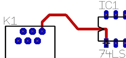
A track in the layout:
You can reach the "Draw track" mode in the layout
by [2] (don't use the "2" in the numbers block of the keyboard) or
by "Draw Tracks" in menu "Elements" or
by the tool ![]() .
.
Leave this mode...
by [ESC] or M12
Placing a signal
When you are in the schematic mode "place wire", press keyboard key [o] (=options) for signal settings, see below. The connections of the components in your schematic are made by signals. In this dialog you can give the signal a name. If you start a signal at the end of another signal, its signal name is continued (e.g. GND). If you start from a free pin, the signal name is derived from the pinname (e.g. A1). If you hit nothing special when starting the signal, a complete artificial signal name is used (e.g. Sig$17). The signal name is shown in the status line.
If you touch another signal with your new signal wire, TARGET 3001! asks, whether you want to concatenate (merge) these two different signals. See below. If you hit the middle of a signal wire, the wire is automatically split into two segments and a junction node is generated. In "Place wire" mode, you can manually place such a junction node too, by pressing [.] (full stop).
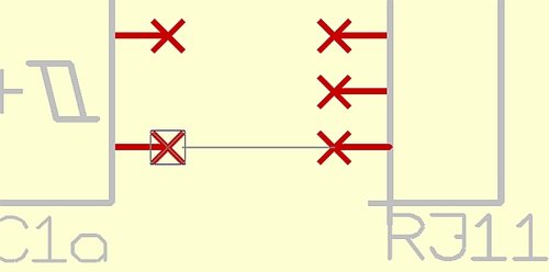
Snap-on-Pin: If you come close to a pin, TARGET 3001! shows a little Snap-on-Pin box, which is like a magnet to attract the cursor. You can avoid this magnetism by pressing [Ctrl]. TARGET generates a beep tone, if you hit a signal or pin correctly. The x-cross on a pins head disappears, if the pin gets connected.
Backspace Function: To delete the last drawn segments of a signal, you can use the [backspace] key. This works like undo and the start position of the cursor gets adapted too.
With M2 or the spacebar while drawing, you can adjust the bending mode of the signal. It toggles between "opposite" bends. An existing signal can be brought in shape by moving segments of it or by dragging its corners.
Connections inside a schematic are made of signal traces. Press the [2] key in your schematic or click on the tool [Image:DrawSignal.jpg]] Place wire to start a signal. In case you hit an already existing signal signal when starting, the signal name of this signal automatically will be continued ( for example: "GND"). When you hit a pin which is not already assigned to a signal, the pin name of that signal will be used as a name for that signal (for example: "A1"). In case you didn`t hit a pin to start the signal, a virtual signal name will be assigned (for example:"SIG$17"). The signal name is displayed in the status line. During the placement of a signal, its attributes can be edited with M11 or [o].
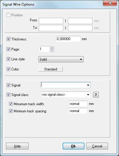
- Thickness: enter the thickness of all future signal segments. This value has consequences regarding the width of later tracks in PCB-layout when autorouting.
- Page: The current schematic page is shown here (can be chosen here).
- Color: Click on the color field for setting the color of your signal track.
- Signal: The pull down menu in section "Signal" shows all existing signals and allows you to select a Signal name.
- Signal class: The pull down menu allows selection from the list of existing signal classes. How to establish Signal classes...
- Minimum track width: Set a value here. "Normal" is equal to the standard setting. This can be found in menu "Settings/Settings (INI file)..."
- Minimum track spacing: Set a value here. "Normal" is equal to the standard setting. This can be found in menu "Settings/Settings (INI file)..."
Bending mode
Please follow the link to have a look: Bending mode
Display of a signal
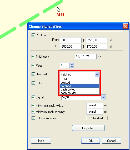
By default a signal in the schematic is displayed as a solid line in green. It is possible to choose different line textures: solid, hatched, dotted, dash-dot, dash-dot-dot. Doubleclick (M11) on the highlighted signal segment and enter to the dialog which opens. See a hatched schematic signal:
When placing signals please note the following rules
Same signal name = same signal! Pins who are not visible connected can belong to the same signal. Check by highlighting: Click in "pointer mode" on this toolbox to select the hit signal segment completely. Afterwards, select the signal segment with M1. The complete signal including all pins will be highlighted. Also, you can use the search function to highlight a signal.
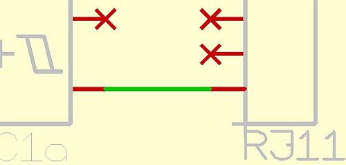
If a connection is made successfully, TARGET 3001! indicates it with a "beep" and the red crosses at the pins disappear. If not, the connection has not been made successfully. In this case, delete the last signal segment with [BACKSPACE] and zoom in with M2. Now place the signal again. The pin-catch-function will be a valuable help to establish a successful connection. While bending signal traces or moving signal segments, connections can also be established or deleted. Direct overlaying pins are not connected. They must be connected at least with a small green signal segment. The following tools are responsible for the marking with M1:
![]() Selects the signal completely
Selects the signal completely
![]() Selects the signal island completely
Selects the signal island completely
![]() Selects only the signal branch
Selects only the signal branch
![]() Selects only the signal segment
Selects only the signal segment
Please find those functions in the extension of the pointer tool.
Signal islands of the same signal which are not connected visually should indicate their belonging by reference symbols. The power-supply connections are a good example. Instead of connecting them to all to the relevant pins, reference symbols are used to show their belonging ( GND- and Vcc- symbols). Also, connections of signals over several schematic pages can be made this way. To start a connection like that, select the according reference symbol with the [R] key.The visible pin name must equal the signal name. You might have to edit the properties of the reference symbol after its import (click with M11 directly on the name text. Attention: A change of the symbol name by clicking with M11 on the handle has no effect. Reference symbols whose name start with an (!), TARGET 3001! will ask for a signal name of choice.
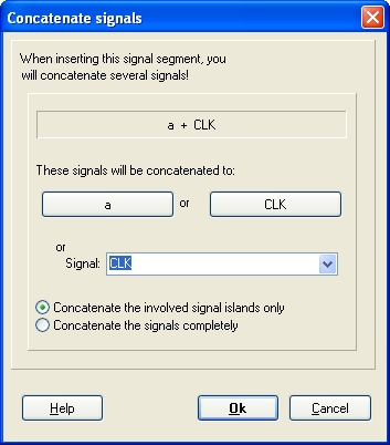
When you try to connect two signals a and CLC for instance as one, TARGET 3001! demands confirmation and asks for a name of the new signal. The following dialog appears:
Do delete a signal completely, please select a signal segment with M1 (please first set: "Selects the Signal Completely" in " pointer mode") , and delete it with [DEL]. You can reverse the deletion with the undo-function. You can also search a signal with the "Search" function (Binoculars).
If you want to split a signal, please delete the connected segments with the [w] and [Delete] keys. Select a segment of the new created signal island with M11 and assign it a new signal.
Signal Properties
please have a look here: Project signals
Signal classes
please have a look here: Signal classes
Splitting and reconnection of signals
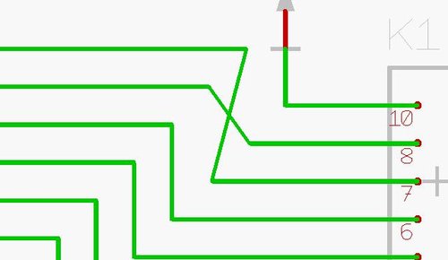
Example: The signals PB6 and PB7 from the example project PIC.T3001 shall be split and exchanged.
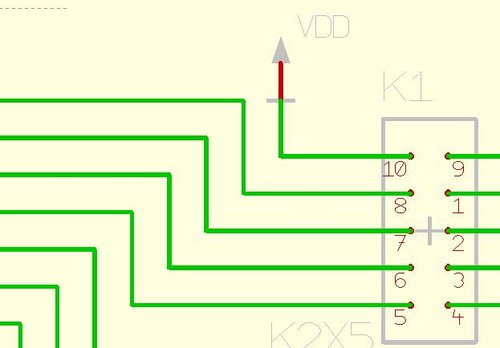
Place the cursor at the marked spots (see above). ![]()
Highlight M1 and delete with [DEL] both signal segments.
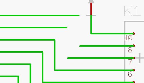
Connect the created endings crosswise. ![]() The dialog "Connect Signals" appears:
Activate the button: "Concatenate the involved signals only "
Select "PB6" in the combo-box (when connecting PB7 with PB6)
Press the OK-key (Return key).
The dialog "Connect Signals" appears:
Activate the button: "Concatenate the involved signals only "
Select "PB6" in the combo-box (when connecting PB7 with PB6)
Press the OK-key (Return key).
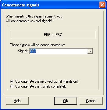
Example on the radiobuttons in the image above: "Concatenate the involved signal islands only" compared to "Concatenate the signals completely" :
You have a signal Vcc, it consists of two islands having two REFerence symbols. Additionally you have a signal Vdd, it consists of five islands having five REFs. At one point you concatenate (connect) Vcc and Vdd and merge it to signal Vcc. If the radiobutton "Concatenate the involved signal islands only" is ticked, only the signal island hit will be merged from Vdd to Vcc. incliuding it's REF. Vdd still exists and now has four islands with REFs.
If the radiobutton "Concatenate the signals completely" is ticked, the complete signal Vdd merges to Vcc, including all REFs. Vdd now does not exist any more.
Rename signal
There are two different ways of renaming a signal:
Rename a signal island: Click M11 on a segment of the island. The following dialog opens:
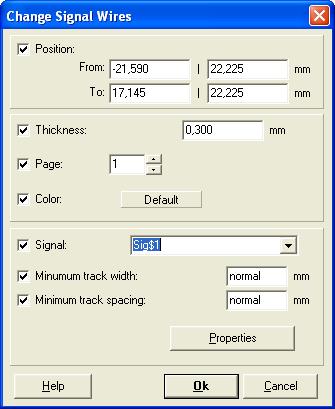
Enter a new signal name or select an existing one. The whole island of that signal (the optically directly connected part) is moved to another or to a new signal.
Rename Signals completely:
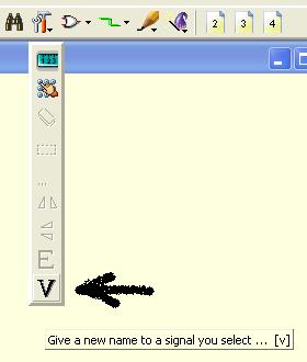
This function renames existing signals with new signal names. It cannot be used to concatenate existing signals. So existing names are rejected. The following dialog is used:
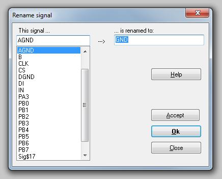
Caution: Changes of signals in the schematic are only transported to the corresponding pads! The tracks remain the old signals. So you can reanimate some tracks by clicking the islands in PCB with M11 and giving them the new signal too. Errors are reported by the design rule check or electrical rule check.
Delete a signal
Search and highlight a signal by the binoculars (search-function) ![]() . If you delete a signal in the schematic view by the use of the [Del] key completely, TARGET asks if you want to delete the corresponding tracks in the PCB view also. If you delete only a part of a signal, no tracks in the PCB view will be deleted. The Check Project function discovers these remainders and displays an alert.
. If you delete a signal in the schematic view by the use of the [Del] key completely, TARGET asks if you want to delete the corresponding tracks in the PCB view also. If you delete only a part of a signal, no tracks in the PCB view will be deleted. The Check Project function discovers these remainders and displays an alert.
Lead a signal over several schematic pages
You can draw your circuit over several schematic pages. The following example shows the logical connection of a signal between the first- and the second schematic page:
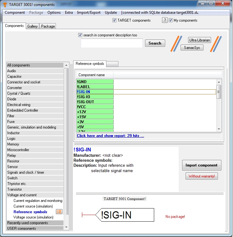
By clicking the "Insert component" icon or just by pressing the [R] key, import the reference symbol "!SIG-OUT" from the component browser to schematic page 1.
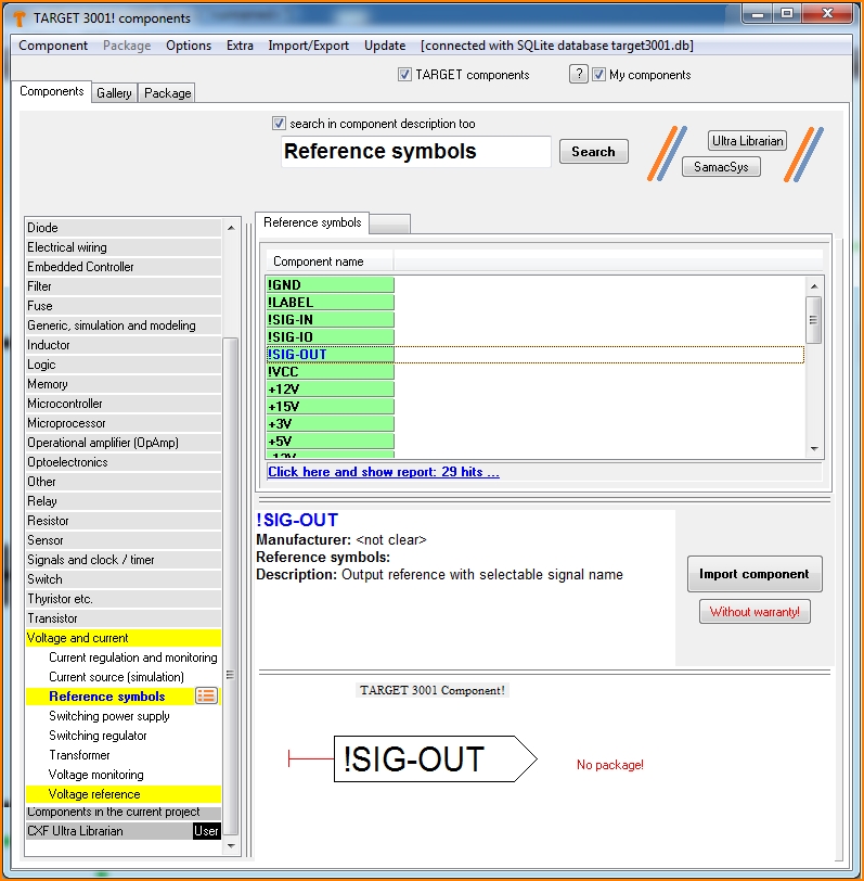
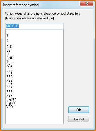
Now you can name the reference symbol with the desired information, i.e. the designated signal name.
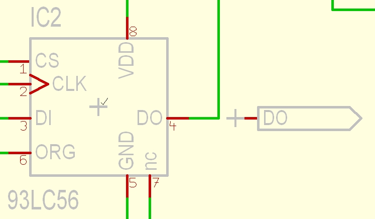
Connect now the signal you wish to lead to page 2 upon schematic page 1 to the reference symbol. If different signal names are touched, you get a dialog to concatenate them to one. If it was DI and you wish it DO then give the advice accordingly in the dialog:
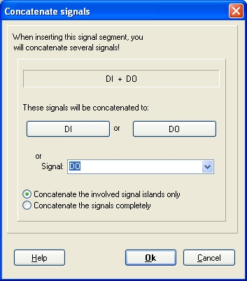
Change to schematic page two with this tool: ![]()
Import a reference symbol (SIG-IN) with the [R] key.
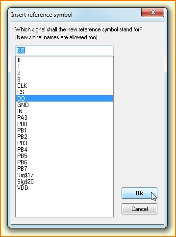
select the signal name from the list or type it in. This is the crucial thing: the identical signal name.
Alternatively click M11 on the text "SIG-IN". The dialog "Change Text" appears.
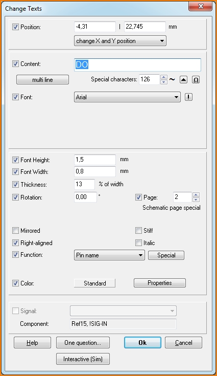
Replace the text "SIG-IN" with the characters "DO" representing the signal in question. A change of the symbol name with M11 on the handle has no influence. Select OK (Return key). To place the signal, press the [2] key directly on the pin. Now draw the signal track.

The following texts appears in the status line (check the correct Signal name...):

Reference symbols with pages of use
A reference symbol can show on which other pages the signal appears. Please have a look here:
Reference symbols with pages
Signal wire options
Doubleclick on a signal or press [o] during the placement of the track to get the following dialog:

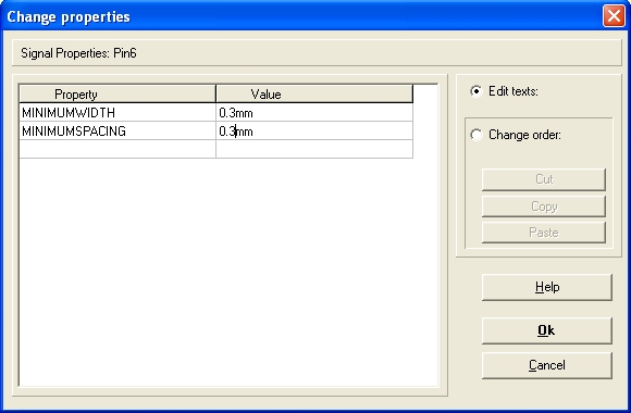
Properties: These are user defined properties of signal wires for the whole signal. Two properties are very important for the autorouter.How wide (thick) a track is routed, is defined here:
Print a list of all signals in use
Please see layout menü Actions/Check and test/Show lengths of signals --> Press the "Save" button and create a list in *.csv format.
See also: Bus | Junction / Node | Pin | Airwires / Ratsnest | Pin swap / Pad swap | Symbol / Gate swap


