Bus
General
A "bus" in TARGET 3001! is a collection (pool) of all signals which appear in a circuit. Buses are distinguished in schematics graphically e.g. as addresses bus [A0…A15], data bus [D0…D7], control bus [Clk, Res, etc.]. You can connect every "signal" to each bus and get it out again later. When you start a signal wire from a bus, a list of all signals is displayed to choose from.

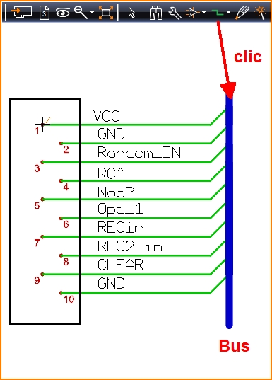
Image: A bus (blue) contains all the signals used in your project. In "Place wire (2)" mode a click on the bus opens a list of signals which allows selecting a signal to lead it out of the bus. It will start from the point where you had clicked.
Draw a bus
You can create a "Bus" by using one of the following methods:
- press [b] (Draw Buses) key while in pointer mode
- by the menu bar and selecting "Elements" then "Draw Buses"
- by
 (Drawing Functions) tool and then the
  (Draw Buses) tool
You can leave this function by "[Esc]" or by clicking M12.
If you wish to place the "Signal Name" beside each of the the signals, hover the mouse to the spot where the signalname shall appear and press the [n] key and follow the dialog. The settings for the Bus can be configured by clicking M11 or by pressing the [o] key while drawing a bus which will open the "Bus option" dialog where the parameters such as thickness and color can be set.
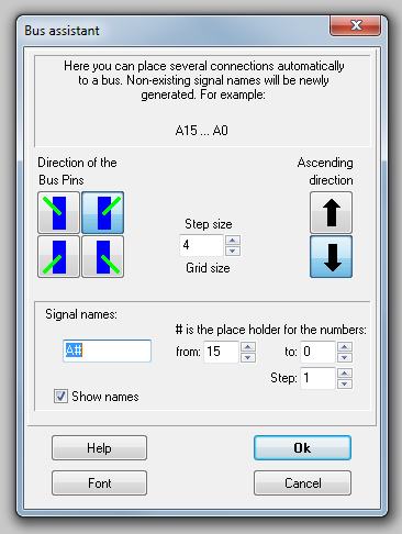
When starting a signal wire from a bus (by clicking M1 or pressing the [2] (place wires) key in "Place Wires" mode) a small dialog will open providing a list of all signal types to choose from, and a button to activate the "Bus Assistant".
Bus Assistant

The "Bus Assistant" automatically connects several signal wires to a Bus. Enter the desired directions, the signal names and the font type. Then press the "Ok" button to begin.
Sources of errors
- In case the signal track not properly is connected to the bus error warnings in the check project routine might occur (Island without Ref.-Pin: Signal .....). Also when exporting to Eagle (r) errors might occur.
- When placing signal tracks coming from out the bus one should select the signal from the dialog box which appears when touching the bus.
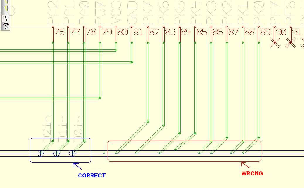
- When placing signals towards the bus please check by the use of the x-ray view (key [#]) whether the bus line has been splitted.
- Signal tracks which already had been placed can not simply be moved onto the bus, because the bus might not get split and the track eventually not is connected properly.
- Please also have a look here: Purple airwires in the schematic

Image: Inspecting bus connections by the use of the hash key [#].

