SMD
|
More info: |
General

A SMD pad besides "wired" ones
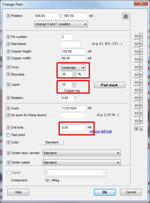
A Surface Mounted Device (SMD) does not have drills (drill hole diameter =0) in its pads and the land pattern only are on one copper side e. g. layer 16, copper top. In TARGET 3001! every component is constructed in top view and that's the way it is saved to the data base. This does not necessarily mean that it needs to be mounted on the top side of the board as well. You can flip it (like any part) to the bottom side of the board by the Mirror command (keyboard key [m]). By default TARGET gets SMD parts into the layout already flipped to the bottom side of the board. You can change this default setting for now and coming projects in the "Package import" dialog.
Construct a CMS pad using a wired pad from the drawing functions or adapt an existing one by clicking M11 on it. Set the
drill hole diameter to zero and change the layer number from
100,all layers to
16,copper top.

Create a SMD pad. Pads can achieve any shape - please use pad form: "polygonal" instead of "rectangle".
Further information on SMD pad construction in TARGET 3001! please read here: Create a component with SMD pads
Declare a package with drills as SMD
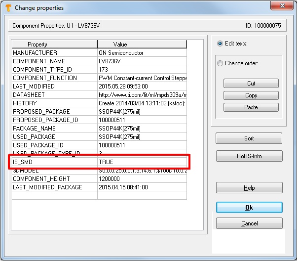
Through holes or vias, or mounting holes within a SMD package makes TARGET think that it would be a wired one (THT). In consequence it would not appear in the pick and place list in the row of the SMD ones which nevertheless might be wanted. In order to get that, you can add the property: "IS_SMD" and set its value "TRUE". Afterwards it can be saved to the data base. But also parts already used in a design can be furnished with this property which counts then alsready.

Image: A non-SMD package can be declared as such by assigning this particular property to it.

