Solder paste
Solder paste is a suspension of solder powder and carrier agens to create a solder deposit upon a pad for soldering in reflow technique (principle: baking oven). Solder paste is needed when components in SMD housings are used in layouts. Solder paste is dispensed in various techniques for example by the use of stencils. The pattern of the soldering pads exactly is cut out of a thin sheet of steel by the use of a laser. The steel sheet with the pattern of holes is the stencil.

A stencil for the application of solder paste
The stencil gets exactly superposed over the PCB and with a doctor knife the solder paste is spread and scraped off the steel. A little bit of the paste remains in the holes over the pads. When the stencil is taken off, these little depots are to be found exactly where they are supposed to be: on the pads.
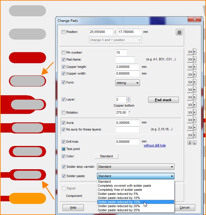
The size of the little solderpaste depots on pads can be edited in TARGET 3001! in the dialog "Change Pads". Open it by doubleclick M11 on a pad. Another way is highlighting the complete layout and then pressing key [e] for edit. Select "Pads" in the flashing dialog and do the solder paste settings in the "Change pads" dialog.
|
Also see: |

Image: The dialog to change a pad, even the mightyness of its solder paste dispension
You may reduce the dispension of solder paste on each pad individually by 5, 10, 15, 20, and 25% relative to the size of the pad. You also may keep pads completely free of solder paste in order to draw a figure of customized (smaller) size on the solder paste layer.
Special application: A customized solder paste shape on a pad
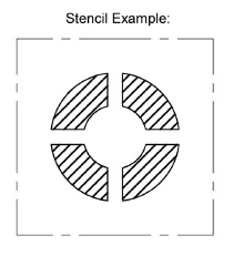
According to the data sheet a circular paste depot on the pad is required with additional 4 ligaments to each side see image:

Image: A special solder paste application (stencil needs to be cut off this way)
In TARGET 3001! the following steps are to be done:
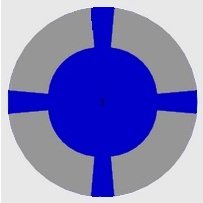
First define a circular pad as an SMD: Take pad from the drawing functions and place it to the canvas. By a double click open it's dialog for edition. Select: Layer 16 (copper top), drill hole diameter = 0,00mm, completetly free from solderpaste. Now draw on layer 19, Solder paste top, a torus of about 90°. The line width is as wide as the ring of solderpaste (in this case it is 1,50mm). In the "Change torus" dialog you need to untick the box "Rounded ends". Now copy the torus three times and place each of it besides the image. By modification of the "Starting angle" and "End angle" of the torus you may turn it to the right position. Now you push it to the soldering pad.
The width of the ligaments can be modified by the start and end angles of the initial torus. For the fact that a torus each is less than 90° the ligaments taper a bit (see image). This can not be adapted.


