Thermal Pads
also see:
- Pad
- Aura
- SMD
- Solder paste
- Solder stop
- Test points
- Oblong hole
- Used pins/pads
- Via
- Drillhole
- Soldering pad having different auras upon different layers
- Two pads leading one signal
See layout "Menu Actions".
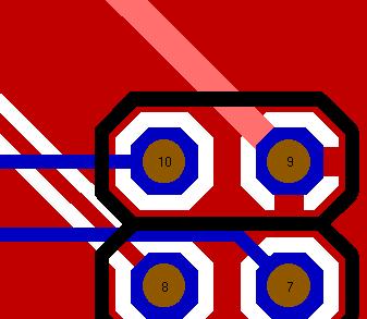
A Thermal Pad (heatsink) means the pad of a component, whose signal is embedded into a signal area (e.g. GND). The pad having an aura, the signal track not having an aura thus connected to the area and the area connected to the signal. The aura of the pad prevents the soldering heat from spreading into the area too quick which might cause bad connection. For example upon layer "Area Bottom 0" or "Area top 14" a ground plane (GND) is drawn. GND-signals running in this area do not have an aura, so they are connected.

Pad No. 9 is connected to the ground plane by its signal track (lighter red because highlighted for visibility). The function "Thermal Pads" is not activated.
For optical reasons the designers intend to break through the aura on further bridges to connect the pad to GND. After highlighting the desired pads click function "Thermal Pads" in layout menu "Actions". In relation to the incoming angle of the signal track to the pad additional connecting joints (ligaments) are generated. The following picture shows the result.

When Signal tracks come in to a pad at angles of 90°, connecting bridges are generated crosswise.

