Schematic: Difference between revisions
No edit summary |
No edit summary |
||
| (4 intermediate revisions by 2 users not shown) | |||
| Line 1: | Line 1: | ||
{|border="0" cellspacing="40" | {|border="0" cellspacing="40" | ||
|[[Image:sch2.png | |[[Image:sch2.png]]||<span class="plainlinks">[[image:miniproject_schematic.jpg|link=http://server.ibfriedrich.com/video/e/miniproject/schem/miniproject_e_schem.mp4]]<br>[http://server.ibfriedrich.com/video/e/miniproject/schem/miniproject_e_schem.mp4 Easy schematic drawing]</span><br><br> | ||
|} | |} | ||
A schematic is a sketch of an electrical logic. It shows the electrical connections between [[symbol|component symbols]] by the use of [[signal|signal wires]] and [[bus|busses]].<br> | A schematic is a sketch of an electrical logic. It shows the electrical connections between [[symbol|component symbols]] by the use of [[signal|signal wires]] and [[bus|busses]].<br> | ||
| Line 11: | Line 11: | ||
*[[Additional_Schematic_Window|more than one schematic]] open at the same time - allows easy cut&paste between designs | *[[Additional_Schematic_Window|more than one schematic]] open at the same time - allows easy cut&paste between designs | ||
*shift highlighted schematic elements to a different schematic page on button click | *shift highlighted schematic elements to a different schematic page on button click | ||
*signal transmission to other circuit diagram page(s) using reference symbols | |||
*extensive SQLite [[Component database]] containing over 40.000 symbols DIN/IEEE locally on your computer | *extensive SQLite [[Component database]] containing over 40.000 symbols DIN/IEEE locally on your computer | ||
*free access to database [[Update|updates]] (internet connection required) | *free access to database [[Update|updates]] (internet connection required) | ||
| Line 16: | Line 17: | ||
*symbols in the schematic can [[Component_editor|freely be edited]] at any time, independently from the database | *symbols in the schematic can [[Component_editor|freely be edited]] at any time, independently from the database | ||
*easy wiring by the use of a [[grid]] and [[Snap_on_Grid|"snap on"-function]] in schematic and layout | *easy wiring by the use of a [[grid]] and [[Snap_on_Grid|"snap on"-function]] in schematic and layout | ||
*acoustic signal confirms correct connection (can be switched off) | |||
*[[Schematic router]] | *[[Schematic router]] | ||
*[[Drawing frame]] predefined | |||
*handle [[Signal classes]] | *handle [[Signal classes]] | ||
*handle [[Differential Pairs ]] | *handle [[Differential Pairs ]] | ||
| Line 24: | Line 27: | ||
*[[Bus|bus-assistant]] for easy placement of similar signals | *[[Bus|bus-assistant]] for easy placement of similar signals | ||
*move a schematic element to back- or foreground (in the context menu) | *move a schematic element to back- or foreground (in the context menu) | ||
* | *functional entities of the schematic can be saved as a functional block | ||
*parts of a schematic or layout can be saved as a [[module]] | *parts of a schematic or layout can be saved as a [[module]] | ||
*easy reworking of a schematic: [[Pin_swap_/_Pad_swap|gate swap, pin swap]] | *easy reworking of a schematic: [[Pin_swap_/_Pad_swap|gate swap, pin swap]] | ||
*[[Rename_signal|renaming]], [[Reorganisation|renumbering]] as well as pin and gate swap automated in schematic and layout | *[[Rename_signal|renaming]], [[Reorganisation|renumbering]] as well as pin and gate swap automated in schematic and layout | ||
*automatic [[Check project|electrical rule check]] | *automatic [[Check project|electrical rule check]] | ||
*read in of [[netlist]]s in OrCAD<nowiki>*</nowiki>-Multiwire and Mentor<nowiki>*</nowiki>-format, TARGET-ASCII and [[Gerber]]<nowiki>*</nowiki>-format | *read in of [[netlist]]s in OrCAD<nowiki>*</nowiki>-Multiwire and Mentor<nowiki>*</nowiki>-format, TARGET-ASCII and [[Gerber]]<nowiki>*</nowiki>-format | ||
*individual creation of [[Bill_of_Material_BOM|BoMs]] and [[netlist|netlists]] in Protel*, OrCAD* and Calay* format | *individual creation of [[Bill_of_Material_BOM|BoMs]] and [[netlist|netlists]] in Protel*, OrCAD* and Calay* format | ||
Latest revision as of 14:02, 14 May 2019
 |
 Easy schematic drawing |
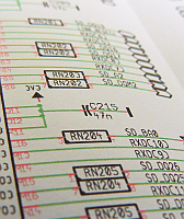
A schematic is a sketch of an electrical logic. It shows the electrical connections between component symbols by the use of signal wires and busses.
Characteristics of the schematic tool in TARGET 3001!:
- each 2m x 2m in size (equals 78.74 x 78.74 inches)
- up to 100 pages in one schematic
- more than one schematic open at the same time - allows easy cut&paste between designs
- shift highlighted schematic elements to a different schematic page on button click
- signal transmission to other circuit diagram page(s) using reference symbols
- extensive SQLite Component database containing over 40.000 symbols DIN/IEEE locally on your computer
- free access to database updates (internet connection required)
- easy component search and placement of symbols with automatic numbering
- symbols in the schematic can freely be edited at any time, independently from the database
- easy wiring by the use of a grid and "snap on"-function in schematic and layout
- acoustic signal confirms correct connection (can be switched off)
- Schematic router
- Drawing frame predefined
- handle Signal classes
- handle Differential Pairs
- variants of assembly supported
- control the impedance of signals in the schematic (Impedance calculator)
- star shaped signals in schematic possible
- bus-assistant for easy placement of similar signals
- move a schematic element to back- or foreground (in the context menu)
- functional entities of the schematic can be saved as a functional block
- parts of a schematic or layout can be saved as a module
- easy reworking of a schematic: gate swap, pin swap
- renaming, renumbering as well as pin and gate swap automated in schematic and layout
- automatic electrical rule check
- read in of netlists in OrCAD*-Multiwire and Mentor*-format, TARGET-ASCII and Gerber*-format
- individual creation of BoMs and netlists in Protel*, OrCAD* and Calay* format
- individual creation of BoMs and netlists for your purchasing dept, for E-Test or assembling automats
with ordering numbers, prices or customized individual properties - parts of the schematic can be copied for other projects
- pSpice compatible simulation included
- your project documentations work in three languages
- images in schematic/layout possible
- printing of the schematic by the print dialog in menu "File".
Special: No forward/backward annotation (re-annotate) between schematic and layout needed. Every change you do in schematic is noticed directly on the PCB side and vice versa. Single source principle. No conflicts of project versions. Easy to learn: Nearly every command identical in schematic and PCB.
The meaning of "schematic" in TARGET 3001!
Talking about the "schematic" in TARGET 3001!, we mean the schematic module. You can reach this "schematic view" by selecting "create new PCB with schematic" in the "Start-Assistent" or by using the icon ![]() (alternative: F3 key) in the layout view to switch to the schematic module.
A schematic in TARGET 3001! can have up to 100 pages. You can distribute signals on multiple pages, therefore you need reference symbols. If a signal in the schematic is connected incorrectly, violet lines appear in the schematic.
(alternative: F3 key) in the layout view to switch to the schematic module.
A schematic in TARGET 3001! can have up to 100 pages. You can distribute signals on multiple pages, therefore you need reference symbols. If a signal in the schematic is connected incorrectly, violet lines appear in the schematic.
If your current window in action is a PCB child window, you can switch back to the schematic window by pressing the key combination [Shift]+[F3]. If a schematic window is already opened, you will be transmitted to it. If not, a new one will be opened. TARGET3001! is able to run 10 windows simultaneously.
Further information:
How to create a schematic in TARGET 3001! (Crash Course)
How to import a component from the library browser
How to wire the pins of a component

