Symbol
General
A symbol in TARGET 3001! is the "schematic fraction" of a component. A component can have one or more symbols (eg. device having multiple gates - each of the gates can get a separate symbol). The other "fraction" of a component is it's package proposal with its 3D model. How to draw a custom symbol and how to assign a package to it, please find in the edit component article.
Import a Symbol
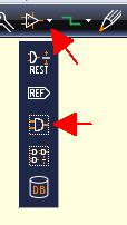
Alternatively press key [Ins] or key [i] or select the command from the menu. This function is used to insert the (first symbol or further) symbol(s) of a component. Open the component database by key [Ins], search for 0,1µF and a 1206 package and have the following image:
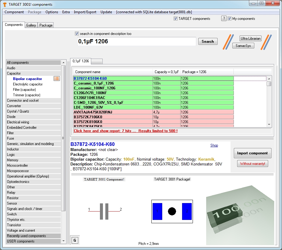
A right mouseclick on one of the three images would allow to edit it. A context menu opens in this respect.
After pressing the button "Import component" it would look like this:
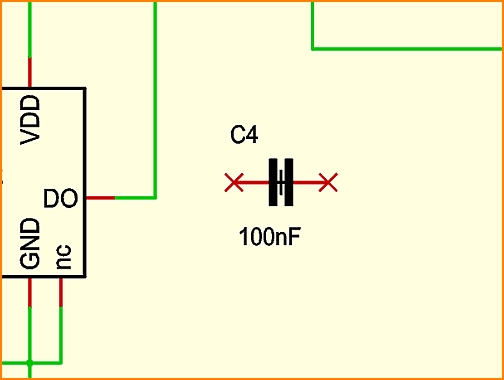
For the fact that already three capacitors have been used in this schematic example, the new one gets number four (= it's component name). The next step would be to connect the pins by the use of the "draw signal" tool ![]() or easily by pressing key [2]. After correct connection the red crosses at the end of the leads will fade. A double click on the handle cross opens the dialog: "Change symbols", a double click on the pin opens the dialog "Change pins". A double click on each of the texts opens the dialog "Change Texts". In case you can not highlight a single part of the symbol but only the whole symbol, please release this button (under the pointer tool):
or easily by pressing key [2]. After correct connection the red crosses at the end of the leads will fade. A double click on the handle cross opens the dialog: "Change symbols", a double click on the pin opens the dialog "Change pins". A double click on each of the texts opens the dialog "Change Texts". In case you can not highlight a single part of the symbol but only the whole symbol, please release this button (under the pointer tool): ![]()
Create a symbol quickly
Please have a look here: Best practise to draw a symbol
or here: Edit component
Compose a symbol
This is a function you need while drawing a new component. It is used because a component in the schematic may consist of one or more (sub-) symbols, e. g. gates. A (sub-) symbol is made of several drawing elements (lines, pins etc.) Select the drawn elements which should belong to this (sub-) symbol and now use this function.
Afterwards, click M1 on the spot where the handle of the symbol should appear. You can also use the [y] key for this function after the cursor has been hovered to the desired location of the handle cross. The cursor should be placed on the spot where the handle should appear. Call the options dialog with M11 or [o] and set the attributes of the symbol to be created next.
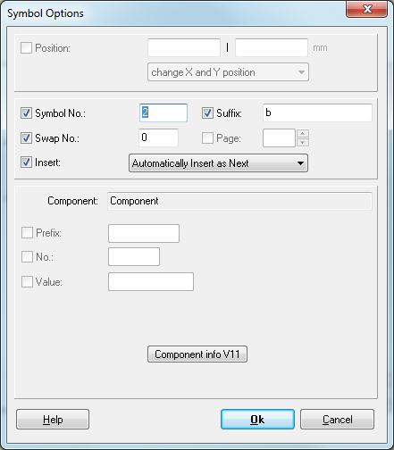
The symbol number should start with one in any case. The suffix is the designator of this symbol (for example: a at IC1a). TARGET 3001! automatically increase the symbol number and the suffix when a new symbol is created. The swap number can only be inserted afterwards by a click with M11 on the symbol handle. A value other than 0 (zero) means: Symbols in a component with the same swap number can be exchanged (symbol change, gate change). The entries for the insertion procedure mode have the following meaning:
Insert automatically as next means that this sub-symbol will be imported into the schematic next, when clicking the mouse again (or if you use Import symbol command again. If all "as next-" sub-symbols of a component are placed, a new component will be fetched in.
Insert extra as Rest means that this sub-symbol will only be imported into the schematic on special request. Mostly these are the power connections. You must place it directly by menu "Components/Import Rest Symbols of Components...".
Swap Number: Symbols, who have the same swap number in the component, can be exchanged with each other (symbol-/gate exchange). The swap number must be greater than 0 (zero). Page: The page where the symbol is currently placed.
Change Symbols
Set the Options or adapt the Properties of existing symbols for components to come here.
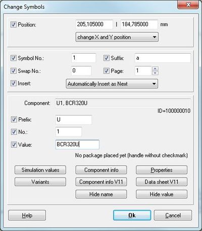
The Position is determined by the x-y- coordinates of the handle cross.
The Symbol No should start with 1 for every component.
The Suffix is the appendage for this symbol (e. g. the "a" in IC1a). Symbol number and suffix are counted further with every new subsymbol. An IC can have several sub symbols - each representing a gate for example.
The Swap No can only be changed afterwards for each gate (sub symbol) individually. A value different from zero means: sub symbols having the same swap number in a component can be exchanged against each other (symbol swap, gate swap).
Page: The schematic page on which the symbol currently is located.
Insert: The entry Automatically insert as next means that the following sub symbol (gate) will be inserted following, as next into the schematic. This attribute will be used for normal gates and for parts consisting only of one symbol. If all "nexts" are inserted, a new part is taken. Extra Insert as "Rest" means that this sub-symbol will be inserted into the schematic only after a separate request by the user. The function required is in menu "Components/Import Rests of Components". You also might use the shortcut [Ctrl]+[r]. This attribute is used e.g. for power supply symbols. NOTE: At least one (sub-)symbol needs to have the property "as next". Otherwise the component might be completely useless.
Component: This line contains the component name and the component value. The component name consists of prefix and component number. Caution: If you change the component's value, maybe the corresponding ordering numbers become invalid.
The text: "No package placed yet (handle without checkmark)" refers to the symbol in the schematic. See below.
Simulation values: Whether a part has a simulation model and if yes which one, please see here. In case it has none you can find information here how to get one.
Component info: If an ordering number of this part is known from various distributors (stored in the component properties you will find them here.
Properties: This is the the information pool of the part. Some properties are predefined. You can also use your individual self defined properties like stock number, internal article number...
Variants: Here you can see whether a part appears in various assembly variants or not. TARGET 3001! can handle up to 256 variants of assembly within one project.
Component info V11: This button offers component information as it was supplied in V11, a special way of these days which we like to keep.
Data sheet V11: If you already in V11 had stored data sheet links concerning a certain part then you will find it here the same way.
Hide/show name, Hide/show value: both buttons are self explanatory. You can fade out component name and -value easily by using the [Del] key. Later you may insert them again by using the Text function "Component name" and "Component value" in the Text dialog.
Checkboxes in front of properties - what do they mean?
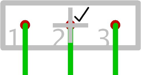
A tick at the handle
The handle cross of a symbol (schematic) gets a tick, if a corresponding package is placed already within the layout.
