Impedance calculator
In high frequency PCB designs the impedance of a signal leading medium needs to be recognized. So it is convenient to determine the later width of a track in the layout already in the schematic. This should be possible for single signals or for signal classes as well. It is about the principle of how a StripLine should be constructed. StripLine.

Image: StripLine (Cross section). The StripLine is the copper in the center.
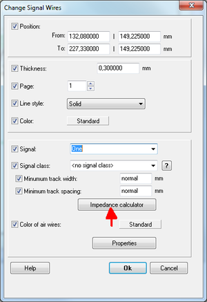
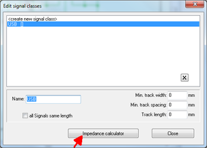
Open in TARGET 3001! the impedance calculator either in the dialog Change signal wires (Double click on a signal wire or press [e] after having highlighted the signal) or in the dialog Edit signal classes (menu Actions).
 Image: The dialog: "Change signal wires" |
 Image: The dialog: "Edit signal classes" |
The following terms are of interest:
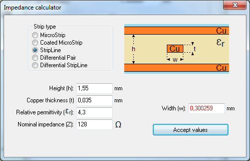
- The hugeness (height) h of the dielectric agens the StripLine is embedded to (= the body of the PCB)
- The copper thickness t of the StripLine
- The permittivity εr of the dielectric agens
A certain Nominal impedance Z required, needs the required track width w according to the the facts given. This track width can be overtaken to the signal or the signal class as standard width.
If the StripLine is placed double (differential StripLine), the distance s between both tracks plays an additional role. The required spacing between the tracks is calculated and overtaken to the signal class definitions as well.

Image: The Impedance calculator suggests the best track width and overtakes the value to a signal or a signal class.

