Aura
also see:
- Pad
- SMD
- Solder paste
- Solder stop
- Test points
- Thermal Pads
- Oblong hole
- Used pins/pads
- Via
- Drillhole
- Soldering pad having different auras upon different layers
- Two pads leading one signal
The aura of a signal leading element is a security spacing towards other signal leading elements. It is defined upon a deletion layer which is related to a certain copper layer. (see Assignment)
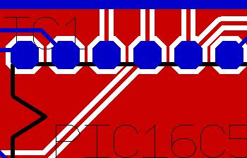
The aura width can be predefined in the "Options" dialog or later by doubleclick on the element within the "Change element" dialog."
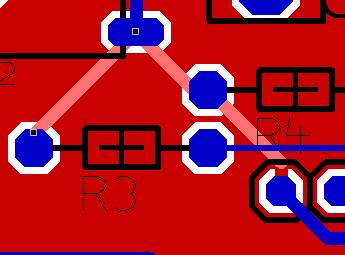
When a signal leading element is embedded into a groundplane, two constellations are possible:
- the signal has a groundplane potential (GND)
- the signal has no groundplane potential, that means it leads a signal different from GND
In the first case, the signal is completely empedded into the groundplane. In the second case the signal needs a spacing to the GND-Signal. We call this spacing "the aura" of a signal.
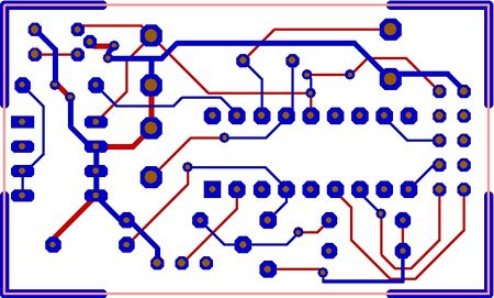
A double sided layout plated through:
When touching a signal leading element, e.g. signal track (1.), via (2.), pad (3.), the aura of the element is displayed in dashed line:
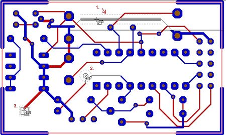
This dashed line which goes along beside the signal line represents a spacing having the the bigger value of both
- the element aura set and
- the minimum spacing of the signal.
But if in the signal's properties the minimum spacing only is set "Normal", the standard spacing is used. This standard spacing is set in "Settings/Settings (Project)" at option "Standard track-spacing (PCB)"
Auras should not touch the copper of other signal leading elements. This will lead to a spacing violation. Auras may overlap.
If you want to colour the aura in a special way you need to give the complete deletion layer the desired colour.
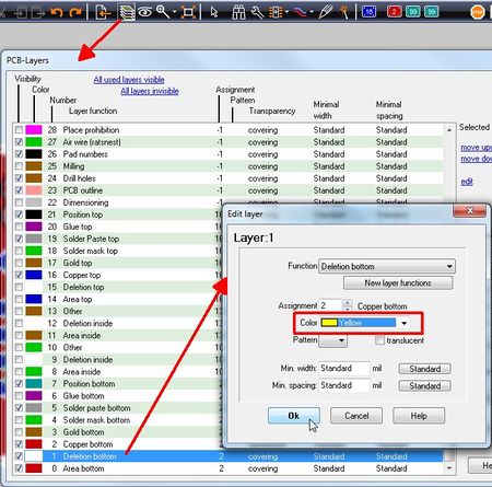
In this example the aura of deletion bottom is white. It should be yellow. Set the colour of layer 1, deletion bottom, from white to yellow by editing the layer dialog. A double click on layer line 1 opens the dialog for edition.

