Connecting the pins
This article is part of an introduction tutorial called CrashCourse2
Download this article as PDF-File
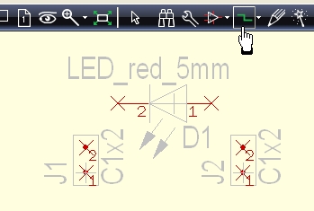
Click M1 into empty space on your schematic to have all parts unmarked. The pins of component symbols are connected by the function "Place wire" using icon ![]()
You can either use keyboard key [2] in order to start this function.
|
More details? |
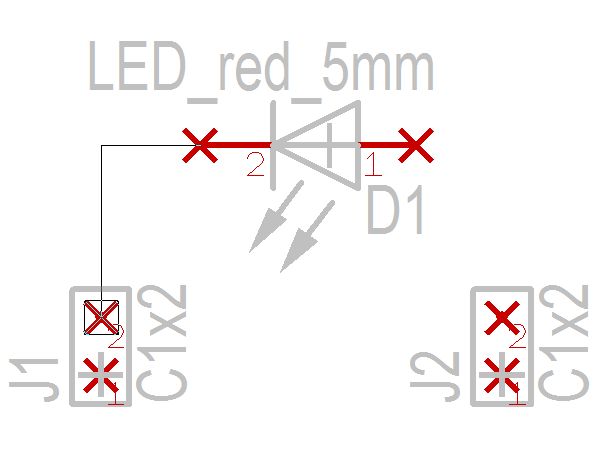
Now lead the signal by M1H from the cathode of the diode to a pin of a connector. The signal has adapted the pin function and leads it further as a signal name. After you have created the connection cut the wire by the use of [Esc] or by M12 to proceed with a new connection. Toggle the bending mode by the use of the "space bar".
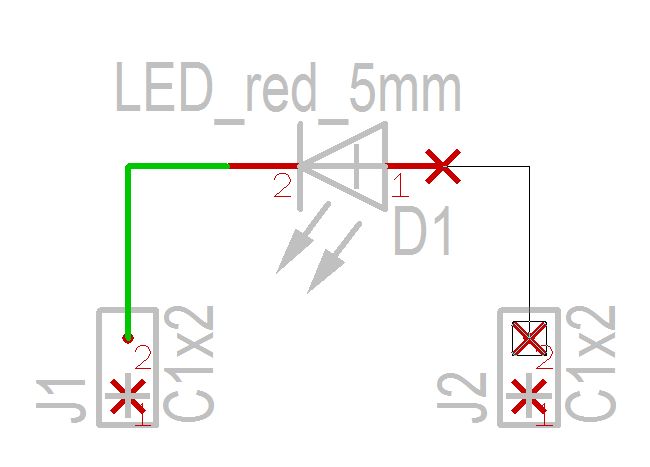
Now connect the anode of the LED...
|
More details? |
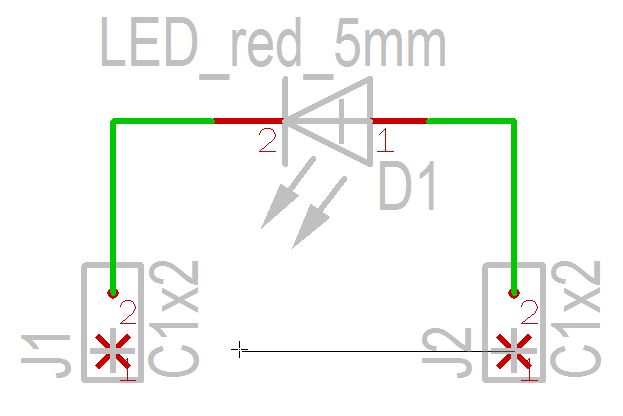
...and connect both remaining pins for ground connection.
The ground signal is connected by a ground symbol. Please find it within the range of "Reference pins" in the sidebar:
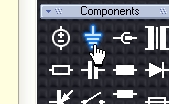
Drag and drop the GND symbol in the schematic by M1H...
|
More details? |
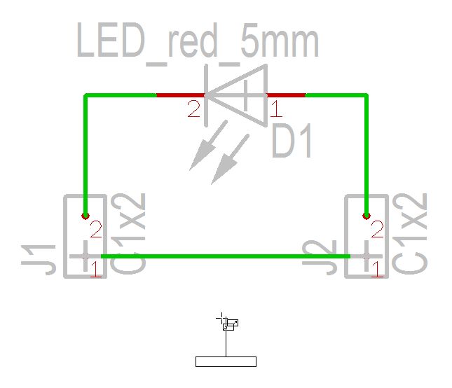
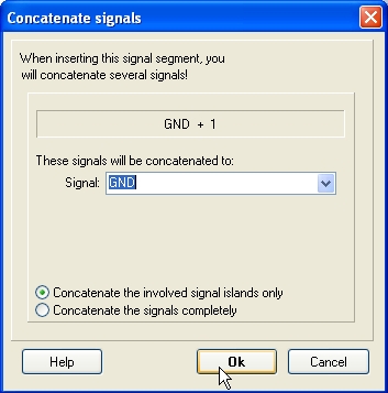
...and connect it that way, that you drag a signal wire from the GND symbol towards the signal track. By this means the signal GND is carried over from the GND-Symbol to the signal track. An intermediate dialog confirms the naming of this signal.
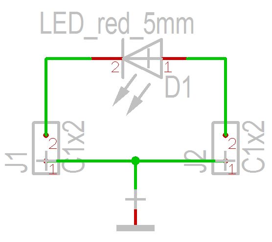
That's what your little schematic now could look like:
