Define a PCB outline
This article is part of an introduction tutorial called CrashCourse2
Download this article as PDF-File
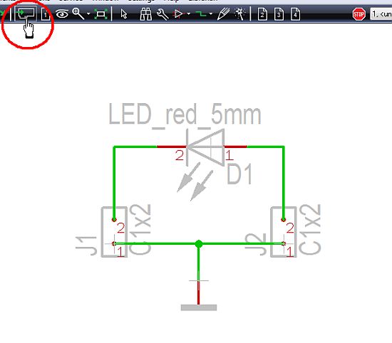
Please switch over to the PCB layout view by the icon "Go to PCB view" ![]() (see cursor in the following image) or use the key F3.
(see cursor in the following image) or use the key F3.

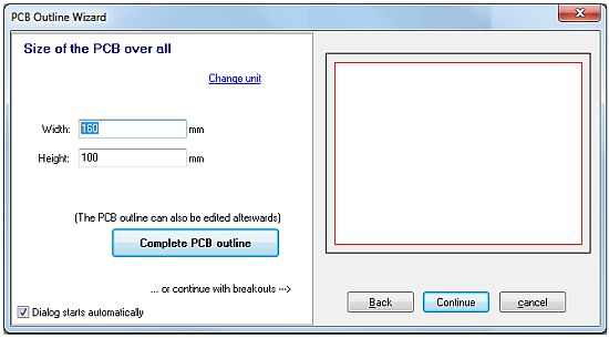
What you see is the PCB outline wizard suggesting a standard PCB outline in light red. It has the measurements of a "Eurocard" (W=160mm, H=100mm). Those measurements are much too big for our little project. Any modification of the outline can automatically be done within the PCB outline wizard in menu "Actions/PCB Outline Wizard":

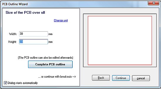
Immediately the assistant opens and we enter Width=30 and Height=20. The fact that we work in metric measurement is default. It can be adjusted to imperial measurement by the "Change unit" link in the dialog itself or by the icon "Adjust View..." (=the eye). ![]() The grid is set at the same location.
The grid is set at the same location.

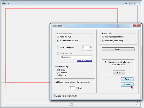
Because we don't have further breakouts at the edges or within the square, we click on button "Complete PCB outline". TARGET 3001! asks whether we want to use the placement wizard which we cancel (we want to place them manually). Immediately the desired outline shape appears on the layout screen. Now we can import the component packages (the footprint pattern, or landmarks) by drag and drop from the sidebar.


