Drawing
In TARGET 3001! schematic drawings, PCB layouts, component symbols and component packages are drawn using specific drawing tools. The drawing tools can be found on the toolbar, by clicking the ![]() (pen) tool.
(pen) tool.
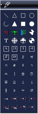
In the schematic view the following drawing functions are offered:

Connection between components in a schematic are drawn using the ![]() (place wires) drawing tool which is found on the left of the pen tool. Also see article for lines.
(place wires) drawing tool which is found on the left of the pen tool. Also see article for lines.
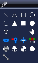
For PCB Layouts the following drawing functions are offered:

In TARGET 3001! the layout drawings are drawn on their respective layers. If you want to draw a copper track, use the ![]() (draw track) tool shown in the layout view, which must be drawn on the copper layer (top or bottom layer). If you want to draw a deletion, it should be drawn on the deletion layer (top or bottom layer). If you want to draw an outline, you must draw it on the outline layer. Any layer can be faded in and out. Please select your active drawing layer using the layer tool. Also see article for Pads.
(draw track) tool shown in the layout view, which must be drawn on the copper layer (top or bottom layer). If you want to draw a deletion, it should be drawn on the deletion layer (top or bottom layer). If you want to draw an outline, you must draw it on the outline layer. Any layer can be faded in and out. Please select your active drawing layer using the layer tool. Also see article for Pads.

