Airwires / Ratsnest
General
Airwires are to be seen only in the layout view (PCB). They represent the electrical connections (signals) between pads and often intersect each other. They are disentangled later by the use of the autorouter or by manual routing. A multitude of airwires are called ratsnest. A basic ratsnest might look like this:
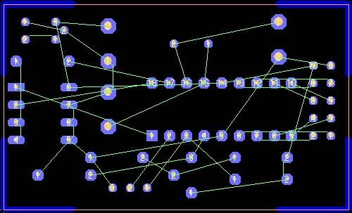
According to the standard settings of TARGET 3001! airwires appear in green. It is possible to adjust the color of airwires, controled by the edition of the signal which is the base for the airwire. There are two situations in TARGET 3001! where airwires appear:
- In a PCB without schematic
- In a PCB with schematic
PCB without schematic
In a PCB without schematic airwires are placed directly in the layout:
by [w] or
by "Draw Air Wires" in menu "Elements" or
by the tool ![]() .
.
Leave this mode...
with [ESC] or M12
Place the airwire by clicking M1 from footprint to footprint. To "cut off" a pad from an airwaire again (delete an airwire), simply click the pad by M11 (in pointer mode) and delete its signal entry. Alternatively, you can select the pad by hovering the mouse over it and pressing key [s] (for select) and edit it by pressing key [e] (for edit). You can not click and edit an airwire itself!
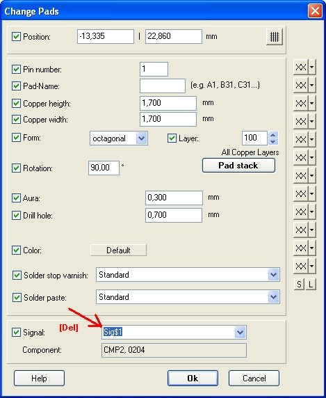
Image: Delete an airwire by deleting the signal at the pad.
PCB with schematic
In a PCB with schematic the electrical connections are made in the schematic by placing signal wires between the pins of the component symbols. After switching to the layout view and after importing the component packages, the connections made in the schematic come out as airwires. For the fact that those airwires intersect each other, this effect is also called a ratsnest.
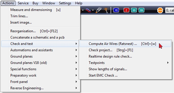
The control of an airwire happens in the schematic. That means that you can't doubleclick an airwire for editing or deleting it. If you want to release a pad from it's airwire, please switch over to the schematic, doubleclick the according pins and delete their signal entries. Is the air wire visible after you disconnected the signal, then first do a "Reorganization" in Menu Actions, then select "Compute air wires (Ratsnest)..." in the "Actions" menu.
From time to time it is necessary to recompute the airwires. Do so by the use of menu:
After selection of this menu entry you'll get the following dialog:
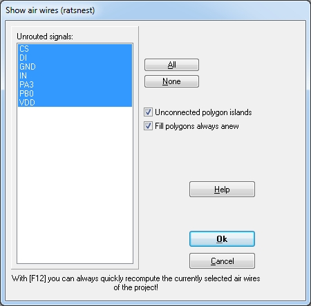
Image: The dialog "Show air wires (ratsnest)". The selection of signals is an example.
With the help of this dialog you can recompute the air wires. Choose an unrouted signal (only the unrouted signals are represented by an airwire) from the list. If there had not been a layer "Air wire" up to now, it is appended at the end of the layer stack and made visible (e.g. upon Layer 27).
For reasons of copper balance during the etching process, it makes sense to let as much copper as possible remain on the board. Thus "Unconnected polygon islands" should remain in the layout. However, one does not want to treat these in the sense of an "error". For unconnected polygon islands you can switch off the air wire display by unticking the box at "Unconnected polygon islands". This leads to a reduction of the air wire display and to a reduction of error messages when using the function "Check project".
Fade in fade out air wires
Open by [Ctrl]+[w] the dialog "Show air wires (ratsnest)". By default all signals are highlighted blue in order to show the air wires. If you only want to see a single air wire highlighted, press none. Click the signal name of the air wires you like to see and press [OK]. A further click turns the highlighting back, thus fades out the air wire.
Airwires in different colors
Using the standard setting, all airwires come out in green. For an easy recognition of a complete signal it is convenient to assign a different color to it's airwire. Maybe you want to follow all connections of a signal optically due to a easier manual routing. As an example we want to color the airwire(s) of a GND signal. First we must highlight the complete signal in the schematic. Prior to this we choose in the pointer tool the highlighting of the complete signal when hitting it:

On click upon any signal segment you now get the complete signal highlighted:
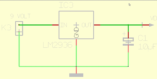
A doubleclick on it opens the dialog "Change signals", which allows the setting of the airwire color:
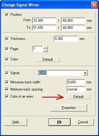
Tick the box "Color of airwires" and click on the button "Default" for deviating from it. The flashing color dialog opens the complete color spectrum:
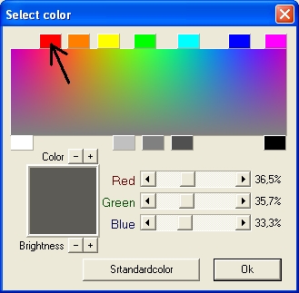
Choose eg a plain red and see the following result in the layout (excerpt):
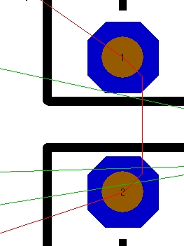
When routing by hand be guided by the color of the airwire for figuring out which parts of the airwire belong to the same signal.
Compute Airwires new
This function in layout Menu Actions recalculates the display of the air wires (ratsnest) at any state of your layout. If your project had no "Air Wires" layer, a layer is generated and attached to the current layers and displayed.
Short airwires are three times wider...
...to see them better:
Help!!! Some airwires lead to empty space and some don't fade even though the signal is deleted...
- Do a "Reorganisation" in Menu Actions.
- If the airwire still remains switch on the x-ray view by pressing the hash key [#] for an examination of your layout in translucent view.
- Are there any redundant track fragments placed by accident? If yes, delete them.
- Do all parts of the track hit each other in the center? (Just slightly touching copper is not enough).
- Drag them to the correct centered position. Set the grid smaller and delete the last misfitting track segment. Draw it new and hit the connecting part in the middle.
- Look at the end of the "orphan" airwire or look at the pad where it starts from: Are there any parts of tracks placed by accident? For the selection of parts which overlap each other please press key [s] several times until a part flashes worth to be deleted (first press [Enter] to highlight it and then press [Del]).
Purple airwires in the schematic
Please have a look here: Purple airwires in the schematic
Number of air wires
How many tracks do I have to rout? By the number of air wires you can say that. This number is shown in the layout dialog "Show air wires (ratsnest)" (from V20). Just press keyboard keys [Ctrl]+[w] to open this dialog.
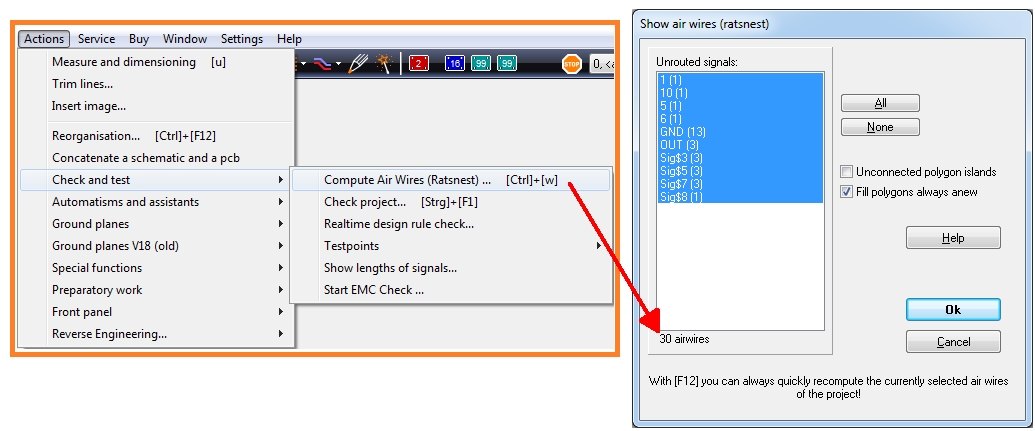
Image: Number of air wires (tracks to be routed).


