Oblong hole
also see:
- Pad
- Aura
- SMD
- Solder paste
- Solder stop
- Test points
- Thermal Pads
- Used pins/pads
- Via
- Drillhole
- Soldering pad having different auras upon different layers
- Two pads leading one signal
Display of an oblong hole in a data sheet
Oblong holes in datasheets often are displayed that way:
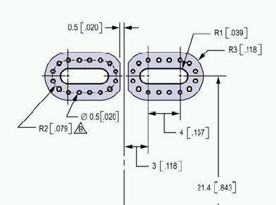
Image 1: Two oblong holes
An oblong hole is a "Drillhole" brought to length. Others call it a slotted drill or a slotted hole. It is manufactured either by nibbling (an iterative number of drills in the dimensions of the desired slot) or by a milling tool. Such tools at least shall be 1 mm strong. In consequence the slot preferrably should be 1 mm wide. Smaller slots are difficult to create. In TARGET 3001! please define millings on layer 25, Milling or on layer 23, Outline because outlines get milled anyway.
Nibbling or milling of an oblong hole?
You define to nibble a slot, which is a well accepted technique when "drilling" oblong holes. Go to the dialog "Create TARGET 3001! CAM-Data" and tick the box "Nibble oblong holes", see image:
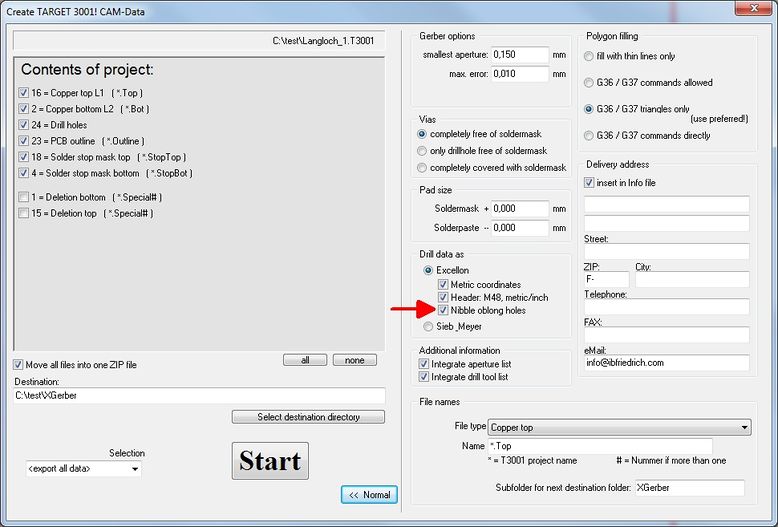
Image: The option: Nibble oblong holes in the dialog "Create TARGET 3001! CAM-Data"
Nibbling leaves eventually a very small inner collar of annuli which might reduce the dimension of the slot. So please add a bit when defining the dimensions of the oblong hole.

Image: The principle of a nibbled slot.
Please regard the inner collar of annuli which might remain fom the drilling. In reality it will be much smaller if at all anything remains. This image is just to illustrate the principle of nibbling (several drills side by side)
To give a pad an oblong hole please use the dialog Change Pads or - a priori - the dialog Pad Options.
Double click on a pad to open the Change Pads dialog. Close to the entry "Drill hole" you'll see the link Oblong hole.
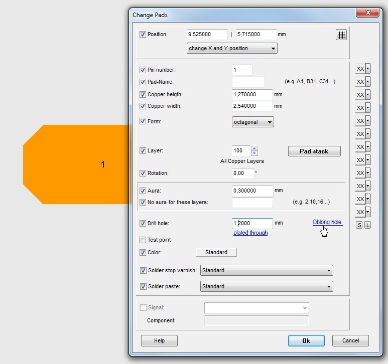
Image: The link: Oblong hole in dialog Change Pads...
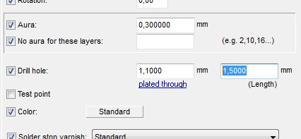
Image: ...allows edition of a slotted hole in horizontal imagination.
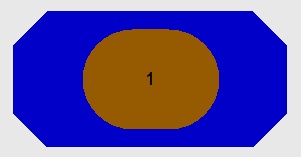
Image: This pad has got an slot (oblong hole) of 1,5mm length and 1,1mm hight. Its height results from the width of the drill i.e. the diameter of the tool. If it is not at least 1 mm wide, the following message appears:
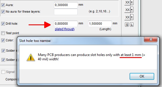
Image: A drill diameter less than 1 mm is too small for many PCB houses.
Alternative:
If an oblong hole shall be surrounded by copper and plated through, please draw a pad showing the desired copper shape and create the oblong hole as a milling. The milling itself please draw as a line having the desired dimensions upon the milling layer (by default layer 25, Milling). Select the drawing tool from the tool bar and press M2 on the milling layer in the side bar in order to activate it. The width/length of the drawn line defines the dimensions of the milling.
The following image shows the principle of creating a lengthened octagonal pad having a drill hole and having a milling command over it on layer 25 (brown). Change the pad form to "Oblong" in the pad dialog.
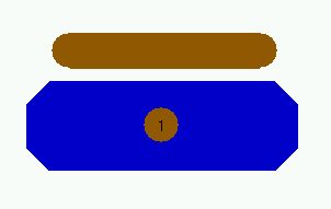
Image 2: An individually shaped pad with a milling command on top of it
Now push the milling in position using M1H.
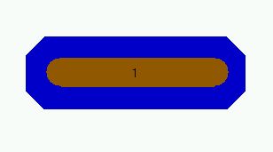
Image 3: A pad with an oblong hole
Your PCB house will mill the oblong hole accordingly. Normally the rule applies: "As long as a copper rest ring remains around the drilling, the figure gets plated through." This is not always the same with milling. Because it depends on the question when the milling will be done: Prior to the plating or afterwards. Regarding the "plating through" in this case please contact your PCB house how they handle such. Maybe you should add a little explanatory text in respect to the milling here.
.

