Difference between revisions of "Text"
(→Elements of the Text dialog) |
(→Elements of the Text dialog) |
||
| Line 31: | Line 31: | ||
'''Page:''' Which schematic page the text shall appear on.<br> | '''Page:''' Which schematic page the text shall appear on.<br> | ||
'''Layer:''' Which layer the text shall appear on.<br> | '''Layer:''' Which layer the text shall appear on.<br> | ||
| − | '''Function:''' When selecting something different to normal text, then the content is adjusted to the text function you assigned. | + | '''Function:''' When selecting something different to normal text, then the content is adjusted to the text function you assigned. See below.<br> |
| − | ''' | + | '''Color:''' A special color for the text.<br> |
| − | + | '''Signal:''' The text can be a signal name and thus belong to the respective signal.<br><br><br><br><br> | |
| − | |||
| − | '''Signal | ||
| − | |||
| − | |||
In '''"Function"''', the following can be selected besides "Normal text":<br><br> | In '''"Function"''', the following can be selected besides "Normal text":<br><br> | ||
*'''Component name''' for the component reference name (e.g. IC17, R15) | *'''Component name''' for the component reference name (e.g. IC17, R15) | ||
Revision as of 12:22, 6 September 2018
Contents
General
You can reach this mode...
by ["] or
by"Text" in menu "Elements" or
by the tool ![]() subsumed under the "pencil" icon (the drawing functions).
subsumed under the "pencil" icon (the drawing functions).
What you can do...
Click M1 to where the text later shall appear. Enter the text and its options to the following dialog. Close the dialog with OK to place the text. Caution: Win 95/98/ME have an old 16-bit graphic, which is not able to mirror Windows fonts. Only the font TARGET can be mirrored in Win 95/98/ME. The Windows fonts can only be mirrored by the 32-bit graphic of Win NT4/2000/XP/Vista.
NOTE: Windows fonts can be mirrored only with the Windows NT4/2000/XP 32-bit graphics. Windows 95/98/ME with its 16-bit graphics can't do this. The TARGET 3001! Gerber driver is not able to output Windows fonts. They are replaced by the font TARGET. Always check the result of this replacement please!
Leave this mode...
by [ESC] or M1
Elements of the Text dialog
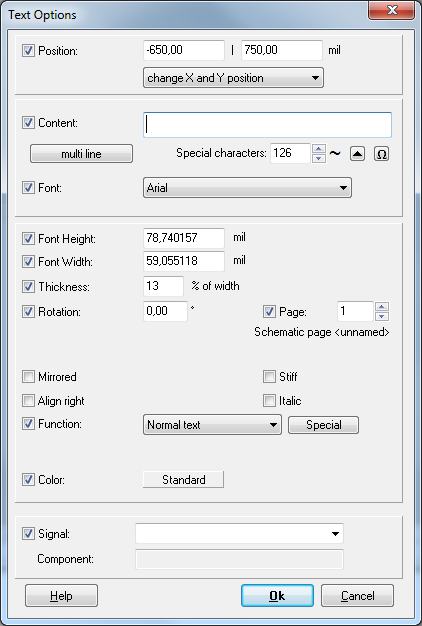
Position: defines the exact location (bottom left) of the text.
Content: allows the entering of your text elements.
Font: Choose any Windows font or extra ANSI characters. Browse the ANSI characters before bringing them to your text by the use of the "arrow up" button. Arial or Times font can be used without worries. It is not for sure that any font will be processed the right way. Check for hight and length of the characters to avoid trouble. If external export drivers (e.g. GERBER) are chosen, additionally the single line font "TARGET" and DIN-ISO-ANSI can be used. Please note that Gerber can only output the TARGET font and that only Windows NT is capable of mirroring Windows fonts. So in the schematic you normally can use any font you like, however be cautious to use Windows fonts in the PCB layout. Often the "Ohm" character is wanted. It has got an own button.
Multiline does what it says: A box opens to enter text in more than one line.
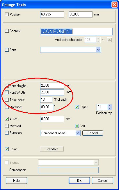
Font Height and Width: define the average measurements of the fonts. The Windows fonts can deviate from this defaults.
When zooming out text at a sudden point can only be displayed as black box. This question of resolution can be controlled in the "Settings / Options" dialog entering a lower value to the "Minimum width" field.
Thickness: applies only if using TARGET font. Windows fonts automatically switch from normal to bold between 10% and 20%.
Rotation: Text or single font characters arbitrarily can be rotated or mirrored. When rotated later by [t] text always behaves the way that it is readable from below or from the right. The checkbox Stiff makes TARGET ignore this rule so that text if rotated by [t] later rotates fixed/stiff according to the angle.
Page: Which schematic page the text shall appear on.
Layer: Which layer the text shall appear on.
Function: When selecting something different to normal text, then the content is adjusted to the text function you assigned. See below.
Color: A special color for the text.
Signal: The text can be a signal name and thus belong to the respective signal.
In "Function", the following can be selected besides "Normal text":
- Component name for the component reference name (e.g. IC17, R15)
- Component value (e.g. NE555, 4k7)
- Symbol name for the symbol reference name(e.g. IC17c)
- Signal name for the name of a signal (e.g. GND, Sig$13)
- Pin name for the name of THEN Pin (e.g. RES\, Pin8)
- Date of change for the last storage date (considers the project variable] DATE_FORMAT if existent)
- Time of change for the last storage time
- Output date for the date of printing or Gerber output (considers the project variable] DATE_FORMAT if existent)
- Output time for the time of printing or Gerber output.
- Scale for the current output scale
- Project name for the name of the project without file extension
- Filename for the name of the project with file extension
- Page number for the current schematic page number.
- Special property for user generated properties
- Variant for the variant name
- Component type for the search name of the component
- Page name for the name of the current schematic page
Multilingual text within one project
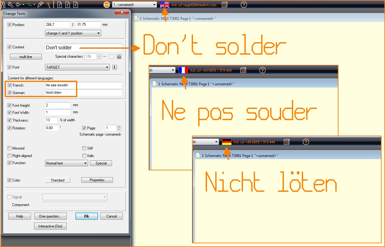
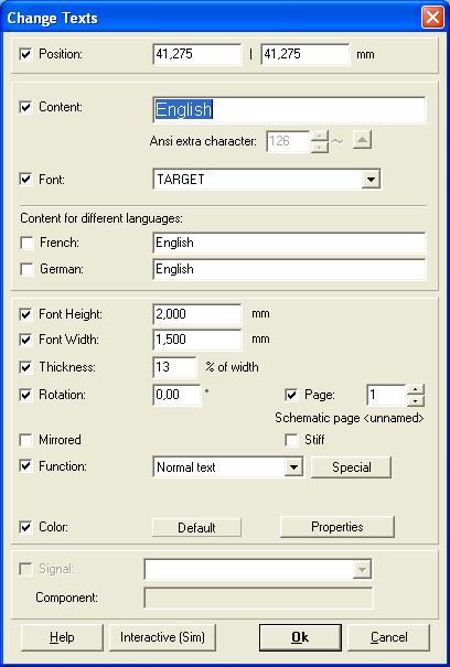
All documentations and text fragments can be edited in three languages, let's say in English, German and in French. After you have placed a lettering in English language (for example the word "English"),
click in schematic or layout double on the text. The following dialog opens:
In section
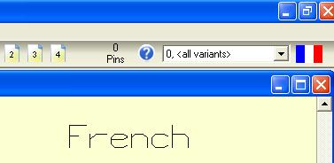
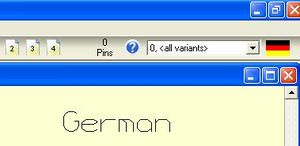
tick the boxes for further languages which you'd like to use and write the text into the lines. For demonstrational reasons we have used the words "French" and "German". If you enter OK, you first see only the English lettering. This is, because you are in the English documentation of the project. Please note the English/American flag on screen.
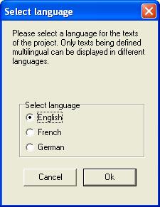
If you click on the flag, the following dialog appears:
Click on a radiobutton to see the letterings in a different language. Viewing the flag, you see which language version you currently work with:
Text can be edited in three languages simultaneously. Which kind of language you use don't matter.
Important note: Multilingual text within one project has nothing to do with "variants". It is a separate, independent text function.
.
Adjust the size of all text elements
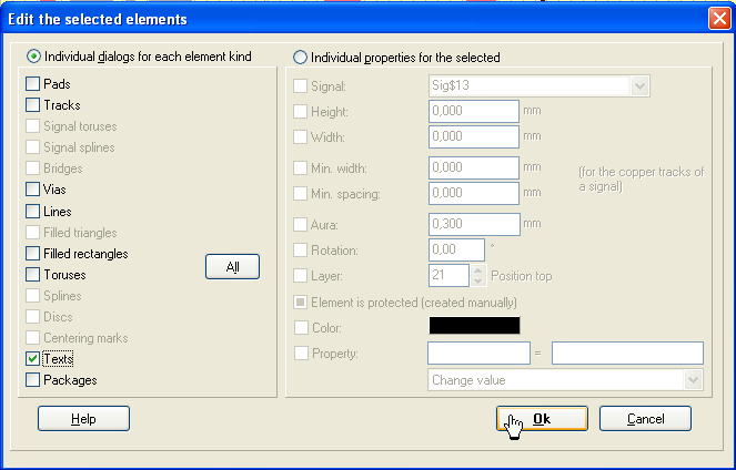
Highlight the complete layout by the use of a Capture Window. Press keyboard key "[e]" for edit. The dialog : "Edit the selected Elements" opens.
Tick the box "Texts" and press OK. The dialog "Change Texts" opens.
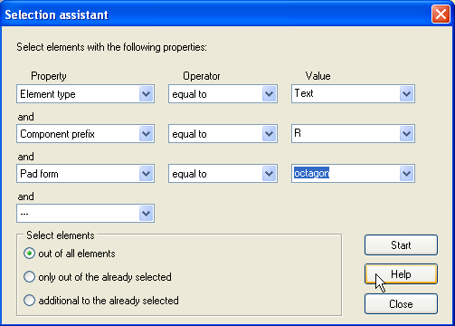
Now do all desired adjustments. If you only want to change (= highlight) certain elements, please use the Selection Assistant in menu "Edit".
Example for the selection of texts of resistors having octagonal pads.
Place a component property as text close to the symbol or package
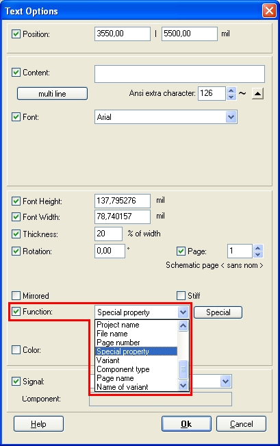
In schematic and layout all properties a component has can be placed like a text aside of the component. First activate the text mode. Hover the cursor over the handle cross of the desired component. Now press keyboard key ["] for opening the text mode dialog "Text Options". Now choose the text function: "Special property" see image (section in red)
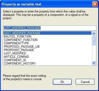
As soon as the special property as a text function is activated, a list opens from which you can select the desired property, e.g. "Last Modified", the date of the latest modification of a part.
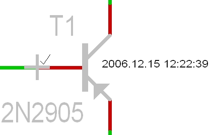
Then press [OK] and confirm the dialog of the "Text Option" too. See the new text in the image below on the right hand side, the LAST MODIFIED - Date. You can select this text, place it at your convenience and change the font.
Please note, that you eventually have to release this button ![]() for touching and selecting only the text. You'll find it in the Sidebar under section Settings.
for touching and selecting only the text. You'll find it in the Sidebar under section Settings.
Einen Kommentar neben ein Bauteil schreiben
Drücken Sie die Tastaturtaste [ß] um den Textdialog zu öffnen. Der Mauszeiger ändert sich und sie sind im Text-Modus.
Klicken Sie M1 an der Stelle, an der die erste Zeile des Textes beginnen soll. Der Textdialog öffnet sich. Drücken Sie den Knopf "mehrzeilig" um nun eine Textbox zu öffnen. Geben Sie hier Ihren Text ein.
Das Ergebnis könnte so aussehen:
Die viereckigen Kästchen der Leerzeilen deuten an, dass es sich um einen zusammenhängenden Text (= Mengentext) handelt. Doppelklicken Sie das Kästchen, um diese Zeile zu editieren. Sie können jede Zeile doppelklicken, um sie zu editieren.
.


