Settings / Options
Contents
General
TARGET 3001! divides Predefinitions (commands for coming actions) from Editions in the sense of changes (ex post/in retrospect).
Predefinitions
Here we speak about "Settings" and "Options".
- Settings control the behaviour of the software in general, e.g. the definition of the library path. You can do the settings:
- by the Context menu (M2 in empty space of the canvas)
- by Menu File
- by Menu Window
- Options are properties of a function effecting coming actions. So first select the function e.g. "Draw track" and then press key [o] (not the "Zero") and do the settings in the dialog "Track Options". Each function has it's own "Options" dialog.
Edit
- Key [e] for edit: use it after having highlighted a design element for adjusting it's properties. The dialog: "Edit the selected elements" allows a more specified selection.
- Doubleclick (M11) on an element opens a context dialog, which allows adjustments of it's properties.
Please also see article Edit.
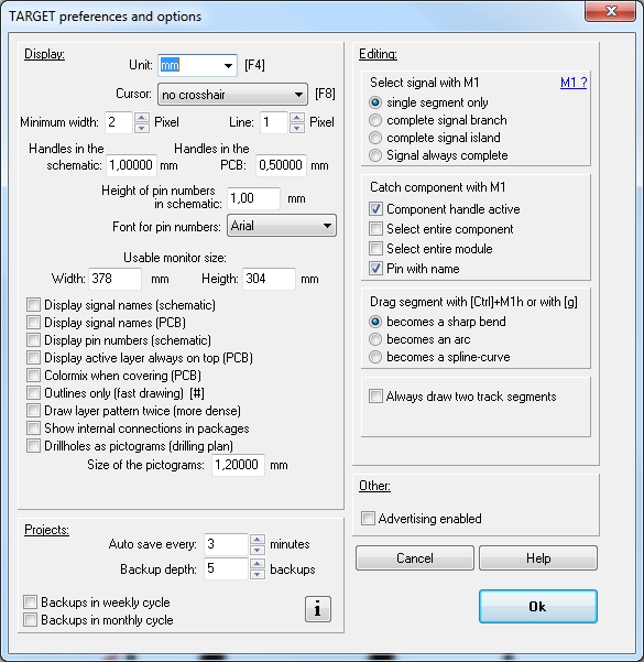
The dialog "Settings / Options"
Open this dialog by the menu "Settings / Settings/Options". Earlier versions of TARGET 3001! offer this option in Menu File/"Settings/Options" or in Menu Window/Settings/Options. After having chosen a working mode you may press keyboard key [o] for Options (not zero) to opt for settings concerning this working mode. Alternatively you also may use a context menu - press M2 in empty space of your schematic /layout.
Here are those settings done, which shall be valid only for the current project or for each new start of TARGET 3001!
The dialog Settings / Options contains several sections:
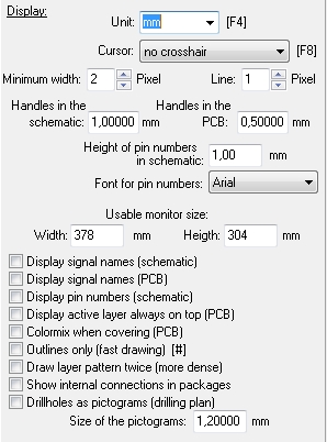
Unit: Choose between the units inch, mil, mm and µm (1 inch = 1" = 25,4mm; 1 mil = 1/1000" = 0,0254mm). This function is identical with the one in the Grid dialog. The entry effects all units within the whole project at all times.
Cursor: The shape of the cursor can be defined
"Crosshair 90°" a full screen crosshair by a horizontal and vertical line.
"90° and 45° " an additional 45° help on the screen.
"No Crosshair" fades out any crosshair. Only the cursor is displayed as a little cross. This one is visible at all times and is not controlled by the grid. It represents a movement by the screen pixels.
Minimum width: controls whether a line is displayed on screen as a filled area or as a pixeled line. Lines representing a very narrow area might get a with of zero caused by internal rounding processes which means they wouldn't be displayed. This can be avoided by entering a value >1 in the field Minimum width. Bigger values support a quicker screen performance but lead to a loss of "truth". This "minimum width" entry also is responsible for the question when a text during zoom out is displayed only as a black box.
Handles in the schematic/PCB: This entry represents the leg length of the symbol-/package- handle, the leg length of the pin crosses in the schematic and the error markers when checking the project.
Hight and font of Pin numbers": Can be set accordingly
Usable monitor size: Please enter here the measurements of your visible screen. TARGET 3001! calculates the screen display that way that 10cm PCB get 10cm on screen. Use your ruler and measure the inner area of your screen and enter the data to this field.
Display signal names (in schematic): Each signal segment gets a label showing the signal name at a predefined small size. In case you wish to have individual signals labeled, hover the mouse on the desired signal segment spot. Now press key [n] and receive the name of this signal displayed at this spot.
Display pin numbers (in schematic): The pin numbers get displayed. More exactly: those ones which haven't been forced to remain faded (set in the Pin's properties).
Display active layer always on top: This is a matter only of the screen view. "Active layer" means the layer which currently allows drawing or writing on. Though it might be one of the lower layer in the layer arrangement, it is made completely visible. regarding the layer logic, please see article Layer.
Colormix when covering (in PCB): In case tracks cover (overlay) each other on different layers their colors get mixed if each of the layers keep the "translucent" property in the layer tool. Having a black PCB background colors mix additively red and blue result purple), having a white background colors mix subtractively (light cyan and light magenta result blue).
Outlines only (fast drawing)[#]: TARGET 3001! draws all solid areas in outlines only. this effects a completely translucent layout. It's a kind of "X-ray view". By the use of the hash key [#] you can toggle both vies (solid/outline only).
Draw layer pattern twice (more dense): TARGET 3001! is able to display the Layers in hatched view. The desired layer need to be set accordingly (see layer tool). All layers predefined for hatched view can be hatched more densely.
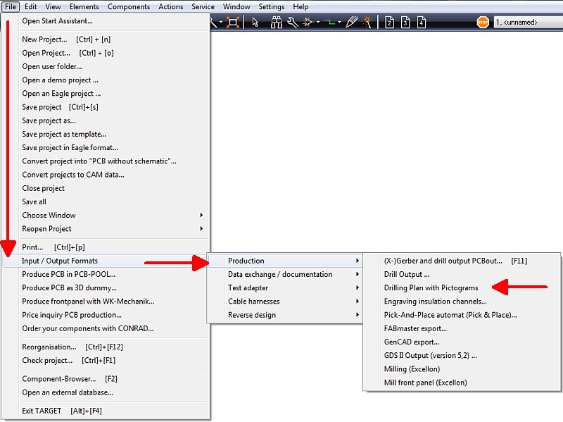
Drill holes as pictograms (drilling plan): In case you intend to drill manually all drill holes in the layout are put out as little pictograms. Identical pictograms represent an identical tool diameter. For creation of the drilling plan select
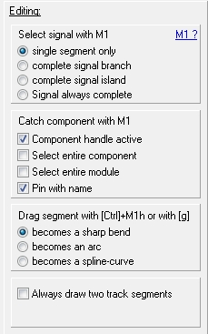
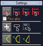
The section top right of the Settings/Options dialog allows the settings for the basic functions of a signal, of a component and the bending modes for the "Pointer view".
single segment only: ![]() ... just the signal segment hit gets highlighted
... just the signal segment hit gets highlighted
complete signal branch: ![]() ... just the signal branch hit gets highlighted
... just the signal branch hit gets highlighted
complete signal island: ![]() ... only the associated signal island gets highlighted
... only the associated signal island gets highlighted
signal always complete: ![]() ... the complete signal of the displayed view gets highlighted
... the complete signal of the displayed view gets highlighted
Component handle active: ![]() ... handle hit highlights the complete symbol resp. package
... handle hit highlights the complete symbol resp. package
Select entire component: ![]() ... any element hit highlights the complete symbol resp. package
... any element hit highlights the complete symbol resp. package
Select entire module: ![]() ... all elements of a module get highlighted
... all elements of a module get highlighted
Pin with name: Some pins in symbols carry their function visible like a name. Highlight it too?
becomes a sharp bend: ![]() ... segment gets split in two (bended)
... segment gets split in two (bended)
becomes an arc: ![]() ... segment gets converted to a curve
... segment gets converted to a curve
becomes a spline-curve: ![]() ... segment gets converted to a Bezier-curve (spline)
... segment gets converted to a Bezier-curve (spline)
Always draw two track segments: repeals the placement delay by one segment. Normally the PhantomImage (pictogram) of a line segment when placing is "one ahead".
Library path
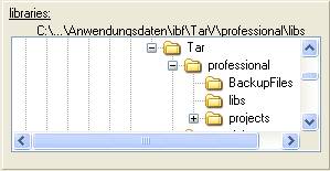
From V15 onward there are no libraries anymore, there is just one database. So you won't find this following section in versions V15 and more recent. Details please see here: Path to the component data base.
V14 and older:
Enter here by tree view which library you want target to search for your desired components. From version 12 onward the standard path for libraries is:
with Win2000 and WinXP:
C:\Documents and Settings\All Users\Application Data\ibf\TarV1X\edition\LIBS
with WIN98, WIN98SE, WIN-ME: C:\WINDOWS\All Users\Application Data\ibf\TarV1X\edition\LIBS
Earlier versions of TARGET 3001!:
C:\Programme\IBF\Target\.
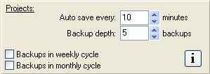
AutoSave: Define a span of 1 to 99 minutes for automatic saving. The current project is automatically saved periodically. It's name gets the suffix .T3001a'. An earlier copy showing the name "X.T3001a" get's renamed to 'X.T3001b'. An entry of zero minutes means "No Autosave".
Backup-Depth: When saving a project, TARGET 3001! creates a copy of it's ancestor. How many of them are created is controled by the digit, entered here. Each of the backups gets the extension .BK*. The asterisk is replaced by the digits 1 ... 9. When the digit is set "2" after several times of saving your Project named "TEST" you have:
TEST.T3001
TEST.BK1
TEST.BK2
Files showing higher numbers are older.
Backups in weekly cycle active: when saving a project on a certain day, a backup is created on the same day of the following weeks.
Backups in monthly cycle active: when saving a project on a certain day, a backup is created on the same day of the following months.
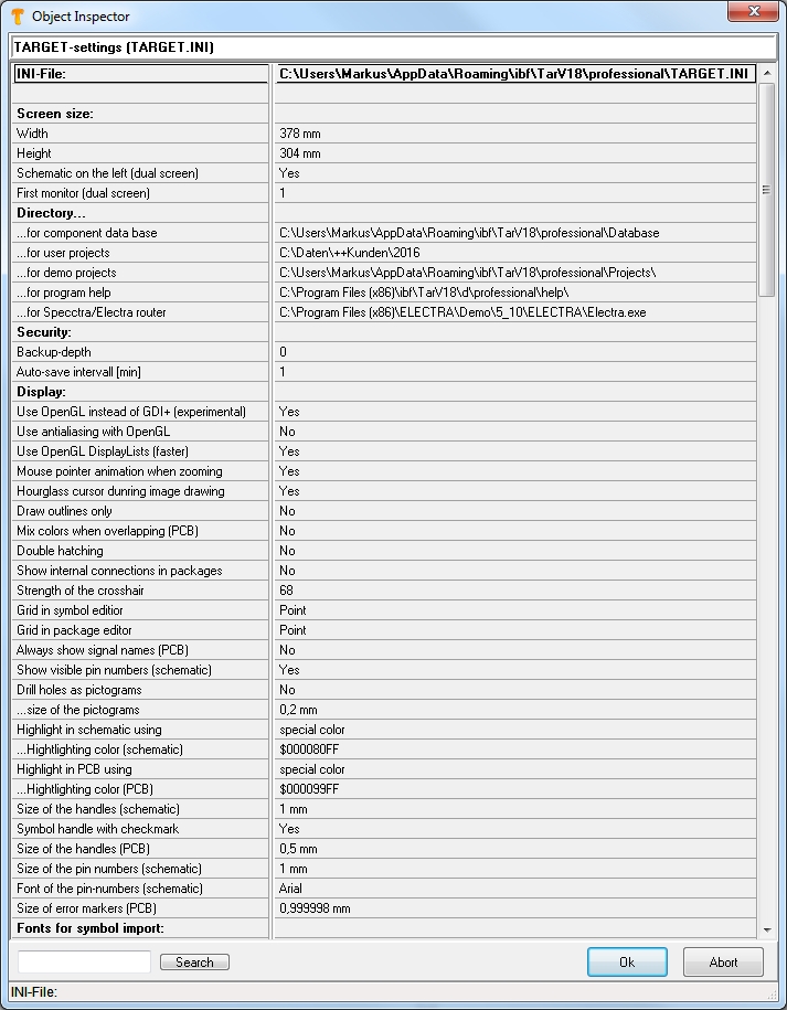
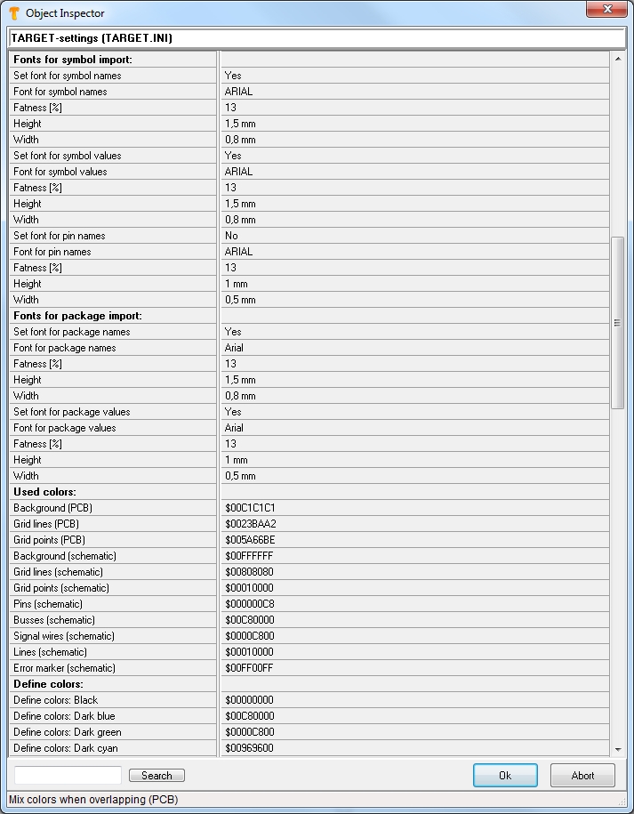
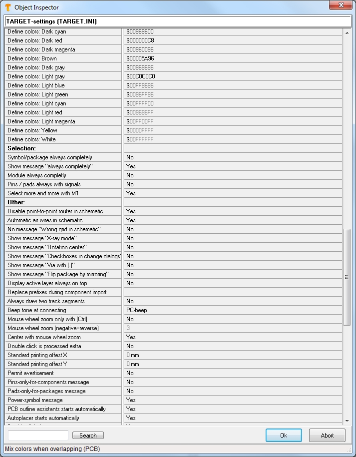
Settings (INI-File)
The settings in the INI-File are saved permanently which means they remain when closing TARGET 3001!. Important: You set your internet connectivity here (at the end of the list). The INI-file is a bare textfile which can be edited with a normal text editor. Please find it by default in: C/Programs/ibf/TarVx/Target.ini
See the following images for getting a glance on what you can set and what will be saved in the INI-File:
Settings (temporarily)
Those settings don't revolve when reopening TARGET 3001!. They show in the default manner.
The contents of this dialog are the same as in the Pointer toolbar:
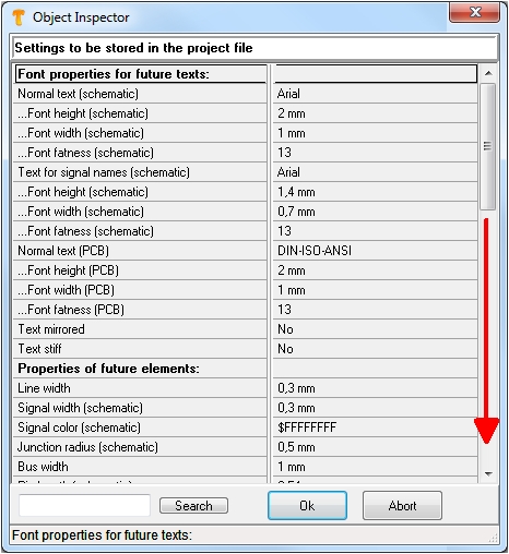
Settings (Project)
Those settings are saved with the project. They revolve when reopening the project. In case you open a new project, the settings of the Default are used. Which options can be chosen please see in the dialog:
In case you are using a proxi server please do the appropriate settings here below (arrow) for internet connectivity...


