Alignment Assistant: Difference between revisions
| Line 105: | Line 105: | ||
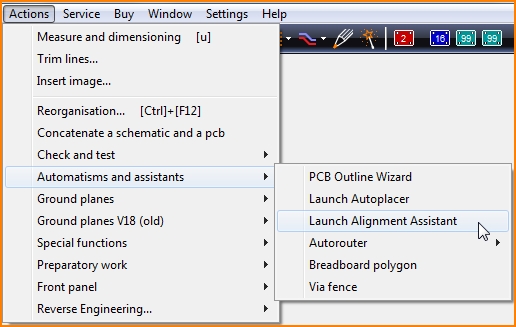
Take a look at the top line: The section after the last comma is the package name. Take the package name to the clipboard by [Ctrl]+[c]. Close this dialog and go to menu '''Actions/Automatisms and assistants''' Choose item '''Launch Alignment Assistant'''.<br><br><br> | Take a look at the top line: The section after the last comma is the package name. Take the package name to the clipboard by [Ctrl]+[c]. Close this dialog and go to menu '''Actions/Automatisms and assistants''' Choose item '''Launch Alignment Assistant'''.<br><br><br> | ||
[[Image: | [[Image:Platzierassi3_e.jpg|none]]<br><br> | ||
Choose a desired alignment pattern, "Radial" in this case .<br><br> | Choose a desired alignment pattern, "Radial" in this case .<br><br> | ||
[[Image: | [[Image:Platzierassi3a_e.jpg]]<br><br> | ||
Revision as of 14:19, 18 September 2018
See also article Alignment
General
See Layout "Menu Actions/Automatisms and assistants" for alignment of packages
or see Schematic Menu Actions for alignment of symbols
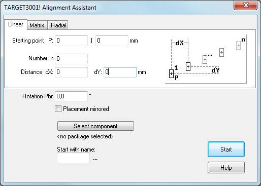
The alignment assistant helps placing components according to special geometrical figures (e.g. 20 LEDs along half a circle). The basic figures: "line" or "matrix" or "circle" are provided. The alignment assistant can be used in schematic or layout view. In most cases it will be used in the layout view. The opening dialog looks like this:
Linear alignment
The logic of this linear placement tool creating a horizontal, vertical or diagonal row of a certain number of the same component types follows this syntax:

The starting point P represents the placement of the handle cross of the first component of the row. dX means the horizontal distance to the handle cross of the next component. dY means the vertical distance to the next component. n means the number of components to be placed in this row.
Enter the coordinates of the desired starting point P as x- and y- coordinates to the first field of the dialog. You can copy the coordinates of the desired starting point from the canvas of your layout to this form by pressing key [Home] after you had hovered the cursor to the desired starting position. Open the assistant again and find the coordinates in the first field. We stayed with the absolute zero in our example.
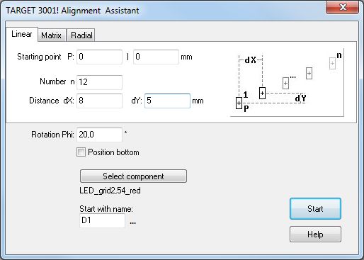
Press the start button in order to receive the following result:
Please note that the package used by the part is named: LED_grid2,54_red. The package name is crucial to know for the Alignment Assistant. We need to pick it from the data baseby the package browser. You will generate the following result:
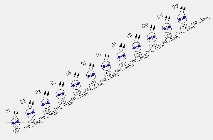
We had predefined a rotation of 20° in a mathematical positive sense (counter clockwise). This might make them easier to connect.
The desired direction of your row please define by using appropriate signs + or - at dX and dY. In the above mentioned example the direction of the row is "north east" because we are moving in an X and Y positive sense. The numbering begins with component number D1, as entered to the dialog. You can enter individual numbers. The component numbering plays an important role regarding the connection of rowed components. Connection of symbols in the schematic and the packages in the layout. When moving from a rowed number of symbols in the schematic to a maybe differently rowed number of packages in the layout you must ignore the package proposals but assign a matching amount of packages having identical component names.
Matrix alignment
Maybe you want to assemble components like rows and columns (a matrix). Please choose the section "Matrix" from the dialog.The starting point P means the coordinates of the handle cross. The number of horizontal rows is defined by "n", the number of vertical columns is defined by m". You must define each in the dialog. The distance between the rows in mm or inch please define by dY, the distance between the columns please define by dX.

Also in this mode you can define a certain degree of rotation "Phi" of all elements of the matrix (rotation in mathematic positive sense) for example 20°. You might also define a mirrored display to assemble upon top or bottom layer.
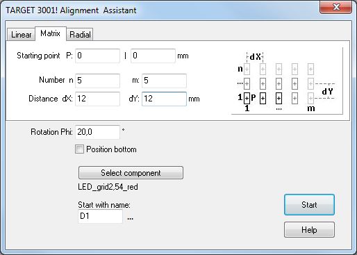
Having selected package LED_grid2,45_red you would reach this:
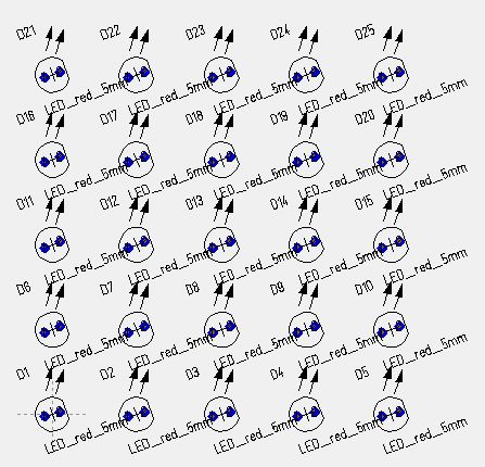
Please note that you can take the coordinates of the starting LED from the cursor position on the schematic. Press key [Pos1] and open placement assistant to copy those coordinates to the field in the assistant.
Radial alignment
For radial assembly of components please choose section "Radial". Prior to this you might have caught the cursor coordinates of the coming center of the circle by pressing [Home] at cursor position. Please enter the number of components to the dialog. The radius R means the distance between center M and the handle cross of a component in mm or inch.

Now you should decide at which degree the circle shall start, which carries your components and how far the angle opens. these options describe the shape of your arc. Enter these values to the fields "Angle from" and "to". This mode of automatic placement allows a gradual rotation Phi of any component relative to its own vertical axis. The settings in the following image...
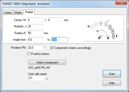
...will have this result:
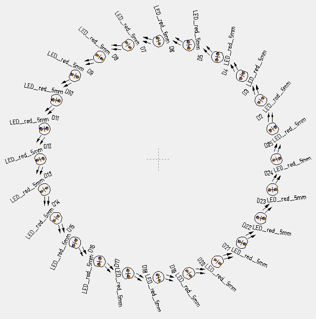
The tick in the field: "Component rotates accordingly" effects, that the rotation of the component is defined by the same angle relative to the radius.
Schematic symbols and the alignment of their package proposals in the layout
You have placed a certain number of identical symbols with identical package proposals in the schematic. Now you wish to align the packages in a special geometric form in the layout. You need the information:
What's the name of the package proposed?
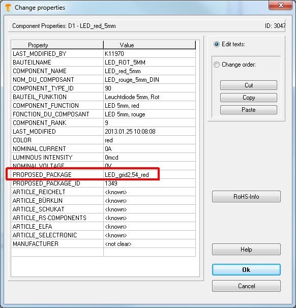
Guess we would have placed 3 LEDs, 5mm, red, named D1, D2 und D3 in the schematic. Doubleclick on one of the handles in order to open the "Change Symbols"- dialog. Click button Properties bottom right of the dialog. The dialog Change properties pops up and gives information on the name of the package proposed.
The name of the package is LED_grid2,54_red.
Now change to the layout view, complete the board outline and cancel the Placement-Assistant. Open menu Actions and Launch the Alignment-Assistant.
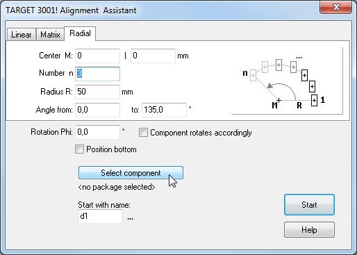
Select mode of alignment for example Radial (see tab) and define the Number n of the packages you wish to align in this case 3. Select Radius and angle and then choose package LED_grid2,54_red using button "Select component". Point at the package from which the alignment shall start, in our case d1.
Three packages named "LED_grid,54_red" now get aligned according to the settings of the dialog starting with d1 and being a sequence (a row of objects). You can define the number of objects as well as the name of the first object. The following components are subsequent d2 and d3. Thus you may define how many objects the sequence has (number n) and from which one it starts (name).
Important note:
If you had 20 red LEDs placed in your schematic you might align e.g. n=7 objects starting with d4 using the Alignment Assistant (d4,d5,d6,d7,d8,d9,d10). But not e.g. d3, d6, d10, d11 and d18.
Layout with schematic: Alignment of the packages in the layout
Say you have placed 12 LEDs red 5mm with an identical package proposal to the schematic. Now you wish to have them placed in half a circle on your layout. Now you need the information Hierzu benötigen Sie die Information:
What is the name of the package proposed by the symbol?
We have n=12 LEDs red, named D1 to D12 placed in the schematic.

Double-click on one of the handle crosses of a symbol and click on the button Properties in the dialogue Change symbols that opens. It gives information about the package proposal in the dialogue Change properties:
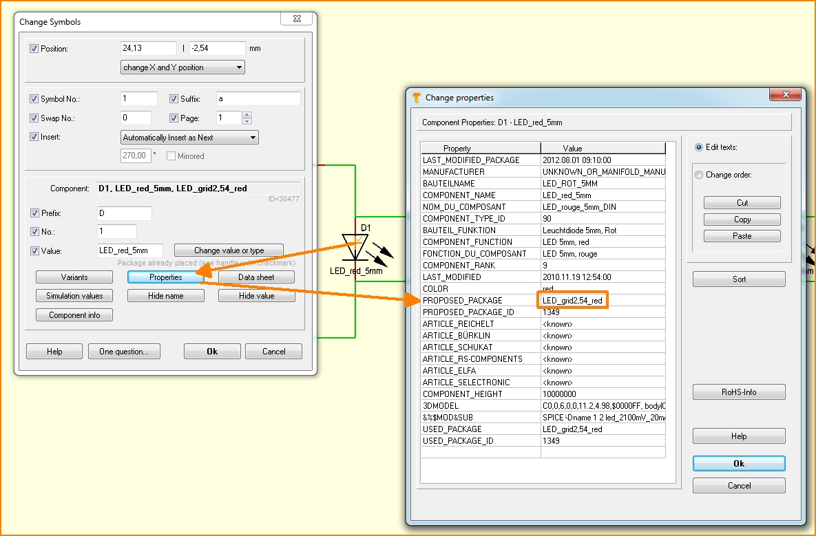
The assigned PROPOSED PACKAGE is named LED_grid2,54_red. Now switch over to the layout. Skip the Outline assistant as well as the Autoplacer, if they would open. First take a look at the dialog: "Import package for".
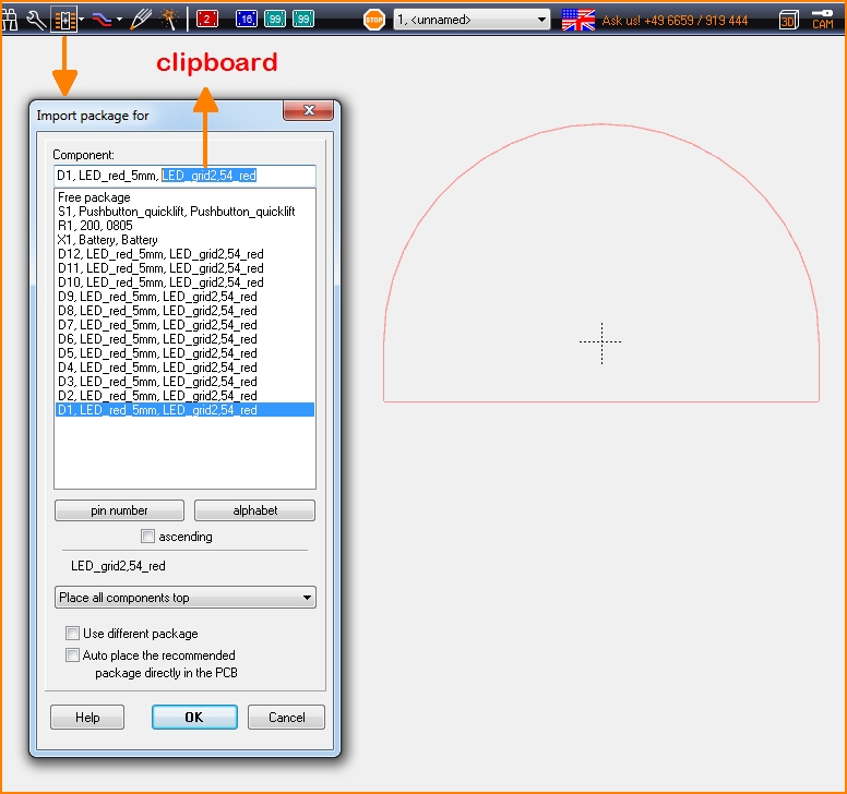
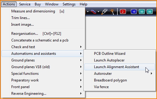
Take a look at the top line: The section after the last comma is the package name. Take the package name to the clipboard by [Ctrl]+[c]. Close this dialog and go to menu Actions/Automatisms and assistants Choose item Launch Alignment Assistant.
Choose a desired alignment pattern, "Radial" in this case .
Bestimmen Sie den Startpunkt mit 0|0, also den absoluten Nullpunkt. Die Anzahl n der auszurichtenden Gehäuse ist 5 und da Sie eine Anornung entlang einer horizontalen Linie mit Griffkreuz-Abstand dX gleich 10mm wünschen, bleibt die Y-Abweichung dY gleich null. Keines der Gehäuse soll um einen bestimmten Winkel gedreht werden, also bleibt auch die Rotation Phi bei null Grad. Bestimmen Sie den Bauteilnamen, mit dem die Folge der Auszurichtenden beginnen soll, in unserem Fall D1 .
Wählen Sie nun aus der Datenbank das eigentliche Gehäuse, bestimmt durch seinen Namen LED_5MM_ROT, indem Sie im Dialog den Button "Bauteil auswählen" drücken.
Es werden nun fünf Gehäuse mit Namen LED_5MM_ROT, die die Vorschlagsliste zur Entnahme aus der Datenbank vorgesehen hat, in der bestimmten linearen Form angeordnet, beginnend mit D1. Gleichzeitig verschwinden diese Gehäuse aus der Vorschlagsliste.
Sollten Sie die Reihe als Ganzes verschieben wollen, ziehen Sie es in Betracht, einen relativen Nullpunkt als Ankerpunkt zu setzen (Taste [Pos 1] am gewüschten Punkt drücken erzeugt den relativen Nullponkt Rel 0|0). Markieren Sie nun die gesamte Reihe mit einem Fangfenster und verschieben Sie sie zum Beispiel mit dem Griffkreuz des ersten Bauteils auf "Rel 0|0".
Info: Es handelt sich hierbei um eine arithmetische Folge (Auflistung fortlaufend nummerierter Glieder). Sie können die Anzahl der Glieder bestimmen und den Namen des ersten Gliedes, z. B. D1. Die weiteren Bauteile sind fortlaufend D2 und D3... Sie können somit bestimmen, mit welchem Glied die Folge beginnt (Name) und wieviele Glieder sie hat (Anzahl n). Hätten Sie 20 rote Leuchtdioden 5mm im Schaltplan platziert, könnten Sie z. B. n=7 Stück beginnend mit D4 mit Hilfe des Platzier-Assistenten ausrichten (D4,D5,D6,D7,D8,D9,D10). Nicht jedoch z.B. sporadisch D3, D6, D10, D11 und D18.


