Torus
Also see: Circle / slice / ring, Snap Point
You select this feature if you need to draw only a segment of a circle (torus).
You can reach this mode...
by [t] or
by "Draw Torusses" in menu "Elements" or
by the tool ![]() .
.
Leave this mode...
by [ESC] or M12
What you can do...
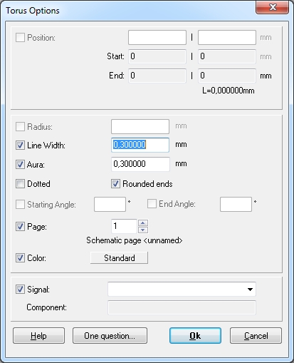
Place the cursor on the starting point of the torus. Press [o] (for options) for torus settings. The second point you are clicking with M1 is the center of the torus and can be entered with [Return] or M1. The third one is the end point. Are point one and three identical, a full circle will be drawn. These arcs are always drawn in mathematical positive sense (counter clockwise). You can call an options dialog with M11 or [o] and enter the following information:

Line width: Width of the torus line.
Aura: Width of the spacing between torus and an automatic ground plane. The torus is also drawn in the according deletion layer. The aura is added to the line width.
Dotted -- Rounded ends: Concerns the line style of the torus.
Layer/Page: Here you define on which page in the schematic or layer of the PCB this one and future tori will be drawn.
Color: Standard means what is set within the ini file. Any other color here can be chosen.
Signal: If the torus is drawn to a copper layer or if it is part of an existing signal, you may either select the signal name here or just view it.
Component: If the torus is part of a component, the component name is shown here. But here you can not actively enter a component name in order to assign the torus to a paricular component.

