Generate a groundplane
This article is part of an introduction tutorial called CrashCourse2
Download this article as PDF-File
A groundplane having the same dimensions like the layout can easily be created by the use of the groundplane assistant, please see layoutmenu "Actions":
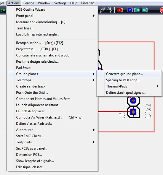
The opening dialog explains that a groundplane in TARGET 3001! is made out of a set of three layers: "copper", "area" and "deletion". The shape of the groundplane is defined on the "area" layer. The "deletion" layer defines the spacings between the groundplane and the non GND-leading tracks. The layer "copper" at least is the one which carries the groundplane and the tracks in copper at the very end. The following example is a groundplane on "copper bottom":
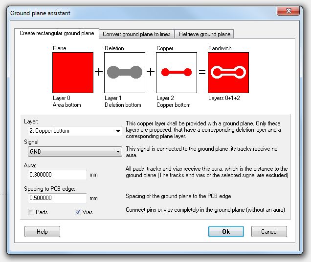
Please confirm the Standard settings and reach the following:
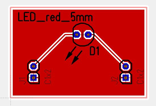
The GND leading track in the south of the layout is embedded completely into the groundplane. Use the hash key (#) for having an x-ray view of the layout. So you can see...
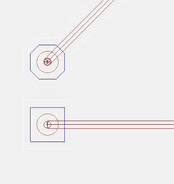
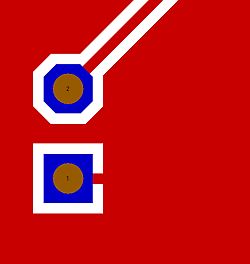
...that the pads seem to be connected correctly. Ant that's the fact (layer 21 position prin,t has been faded out = the colored field at layer 21 was unticked).
The generation of thermal pads is managed by highlighting the complete layout and choose menu "Actions/Ground planes/Thermal Pads/Create Thermal Pads". Pads whose signal tracks are embedded to the ground plane, receive two or three further ligaments. Result:
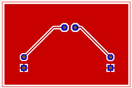
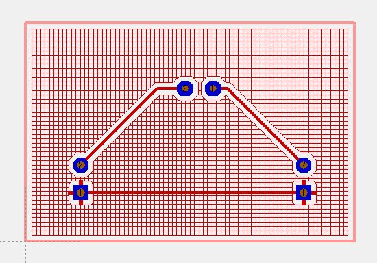
The groundplane can also be transferred to a grid. Please again open the ground plane assistant (menu "Actions/Ground planes/Generating a ground plane") and choose the tab in the middle:
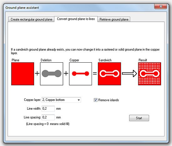
After pressing the "Start"-button, we receive:
