Simulate the function Part 1
This article is part of an introduction tutorial called CrashCourse2
Download this article as PDF-File
The simulation in TARGET 3001! is a matter of the schematic, so we switch over to it:
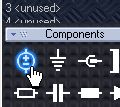
In order to simulate the LED function we need a voltage source, and a load resistance. Those components will not be part of the layout therefore they don't have a package. Find such components in the database. See sidebar icon:
It will open the component browser close to the sources. Select the V_SINUS and import it:
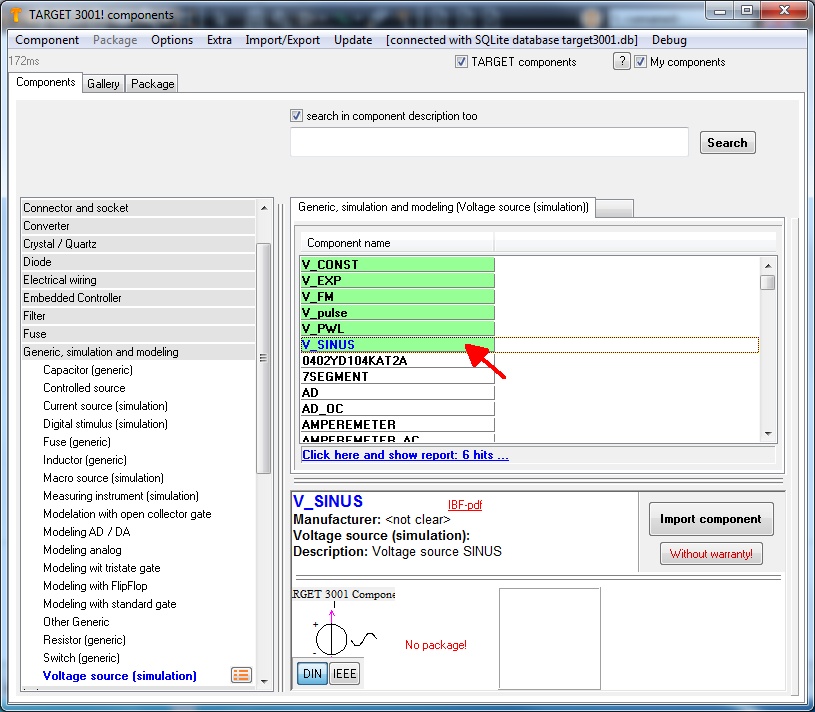
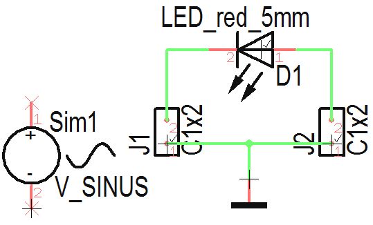
After we have placed it, the schamatic might look that way:
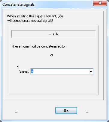
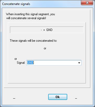
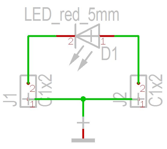
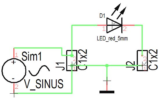
Following the convention that in a schematic the sources should be on the left hand side it is necessary to rotate the diode because we have to recognise it's polarity. Delete the connections then touch and hold the diode at it's handle cross M1H. Press right mouse key M2 two times in order to rotate it. Now connect it new. Reduce the size of the font by a double click each on the text and entering to the dialog smaller font hights and widths. Connect the source pins towards the connector pins and confirm each the suggested signal names (+) and (GND).
That's the way the schematic looks now:
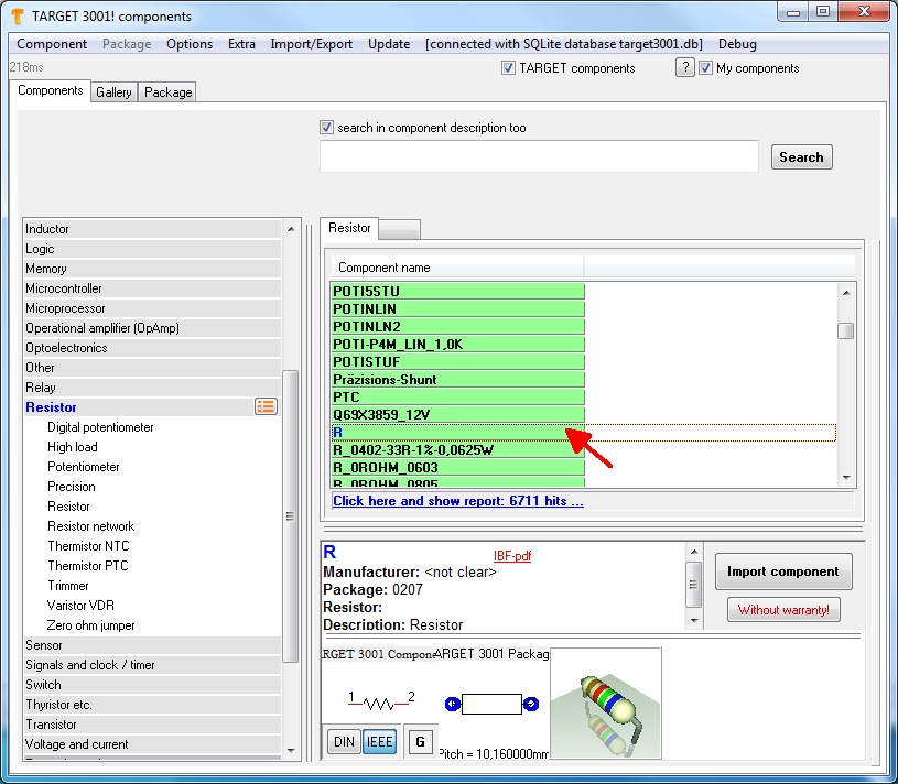
The load resistance we pick from the database. Open it by the key [Ins] and enter a bare "R" to the search line of the "Quick select" tab.
Import it to the schematic and and connect it accordingly. Having done some font adjustments the schematic now might look like this:
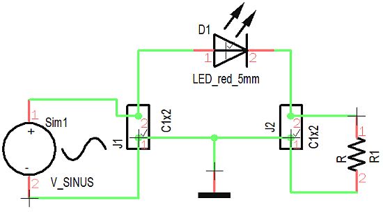
Now we set the values for source and load, first M11 on the handle cross of the resistor. Now we enter component value "200", this stands for 200 Ohm:
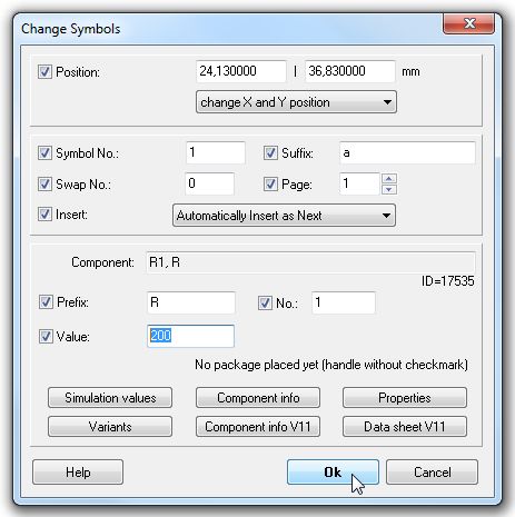
Press OK. Now press M11 upon the handle cross of the sinus source:
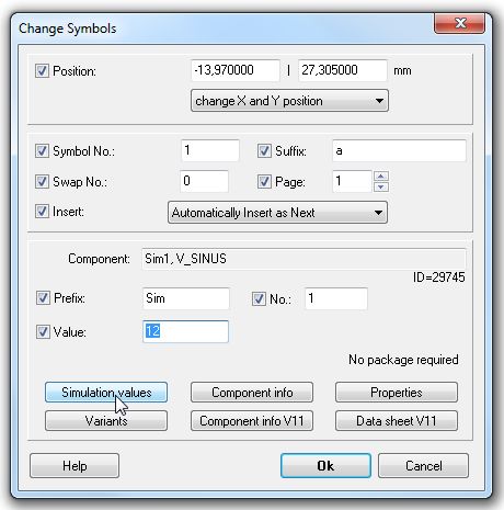
We define it's component value by 12 (meant is 12 V). By the use of the "Simulation values" button in the same dialog we set the frequency. In the following dialog press button "Edit". Afterwards a setting of the parameters can be done:
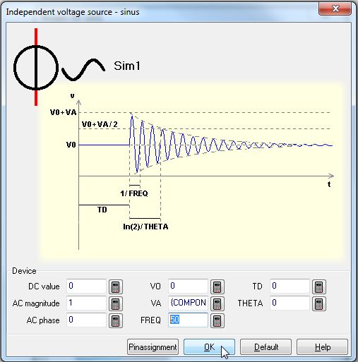
At "FREQ" enter value 50. Now the preliminaries are done. We confirm all dialogs and the schematic is ready for simulation.


