Freehand groundplane
Also see article Groundplane
Generating a custom groundplane
Example: A groundplane on the bottom side of the board needs Layer "2=copper bottom", "1=deletion, assigned to layer 2" and "0=area, assigned to layer 2. The following images show the process of how to create a polygon-shaped groundplane on the bottom layer.
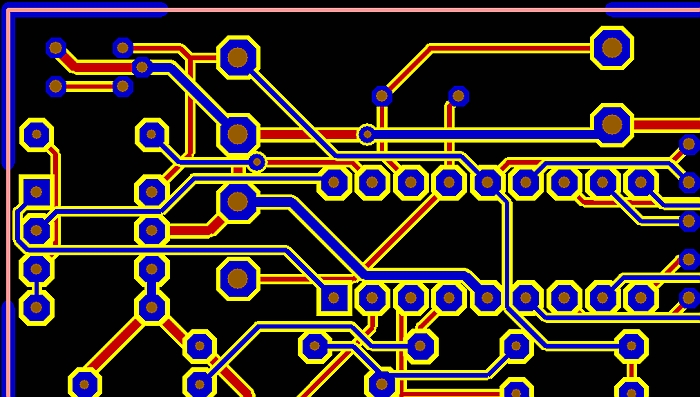
The first step is to have all signals routed (the GND signal too). In this example black is the background of the screen, red is copper bottom, blue is copper top, yellow is the spacing any track has by default, the aura, what we call it(0.3mm).
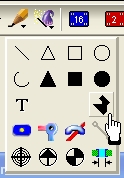
Now we want to create a groundplane which has the shape of a polygon upon the bottom layer. So the next step is to select the polygon tool from the drawing tools:
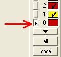
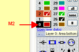
The shape of any groundplane is defined and displayed upon an "Area-" layer. For we want to have the groundplane upon the bottom layer, we choose layer 0=Area bottom for the drawing.
From Version 14 on you activate a layer for drawing by clicking M2 on the layer number in the sidebar:
Now we draw the polygon by several mouseclicks. The shape is just an example. Sure you also can use the "filled rectangle" or the "filled circle or triangle" tool.
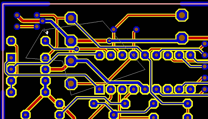
After a final M1 click it appears in solid red, because it is the color assigned to layer 0.
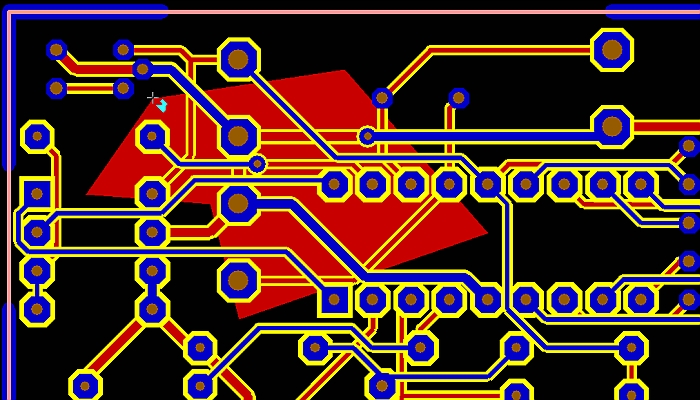
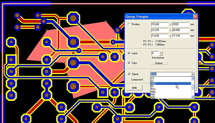
Now we must assign signal GND to this figure. So we highlight the complete figure (it appears in light red) and press key [e] for "edit". We select the GND-signal from the list.
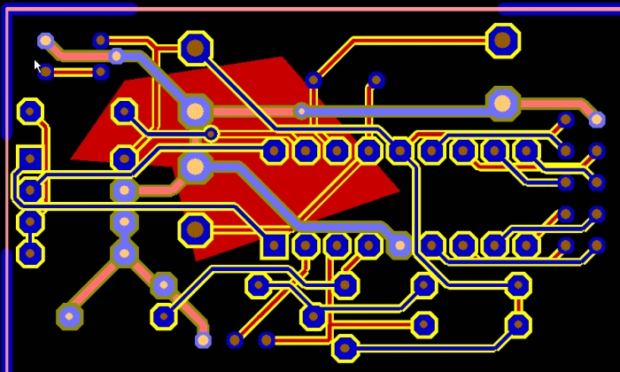
The next step is to connect the GND-tracks which run through it. We do so by taking away the spacing (the aura) by setting it to zero. First we should highlight the complete GND-signal, by the use of the search and select function:
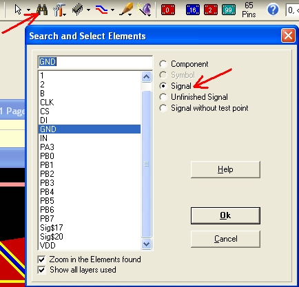
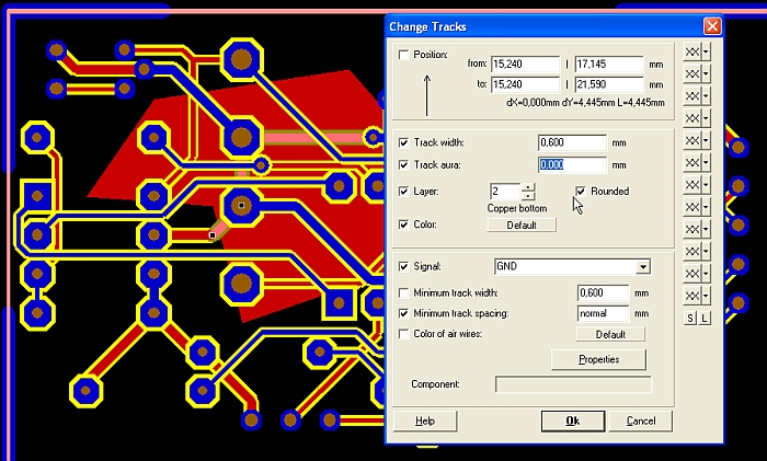
Now we see the GND signal, highlight the GND segments which run through the groundplane by [Shift]+[[[MousekeysM1]]] and again press [e] for editing the signal.
We set the track aura to zero...
and get the following result:
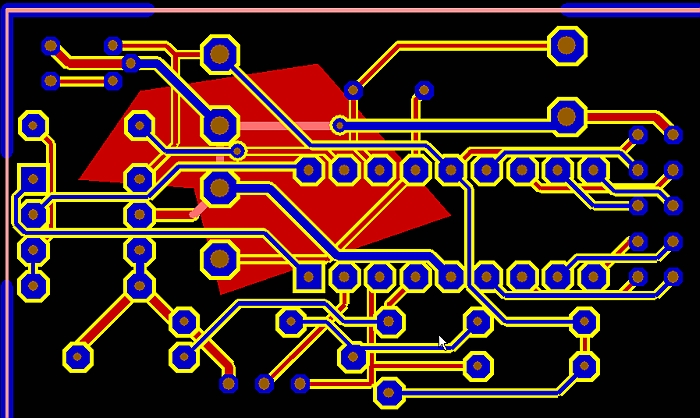
The segments still are highlighted, this is the reason why they still are in lighter red. After a M1 click to anywhere the segments are embedded to the polygon.
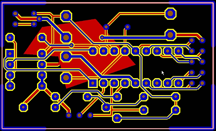
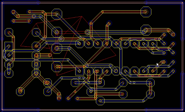
For inspection you might use the hash key [#] key to toggle between X-ray view and solid view of your layout:
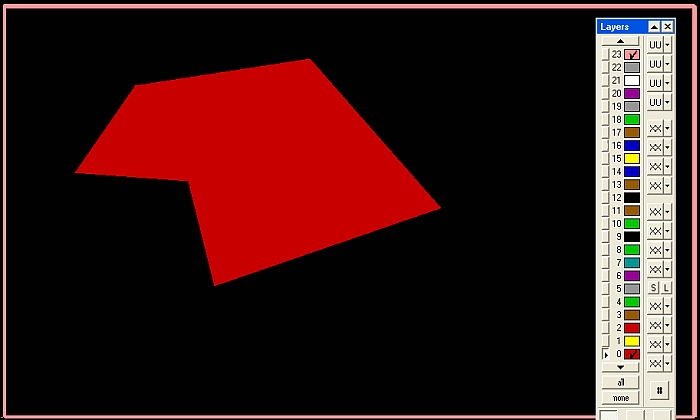
Now you might inspect each of the layers involved. Click on the "none" button at the bottom of the layers tool to fade all layers out. Now tick the colored box of a desired layer and hover the cursor in again. First see Layer "0=Area bottom":
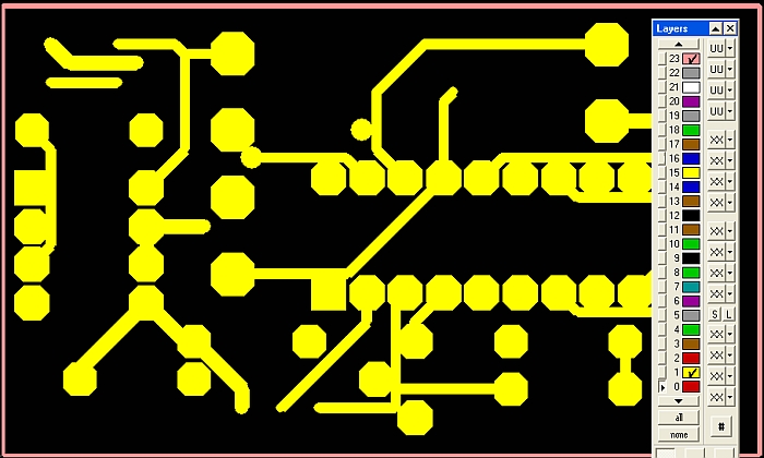
Then see layer "1=Deletion bottom":
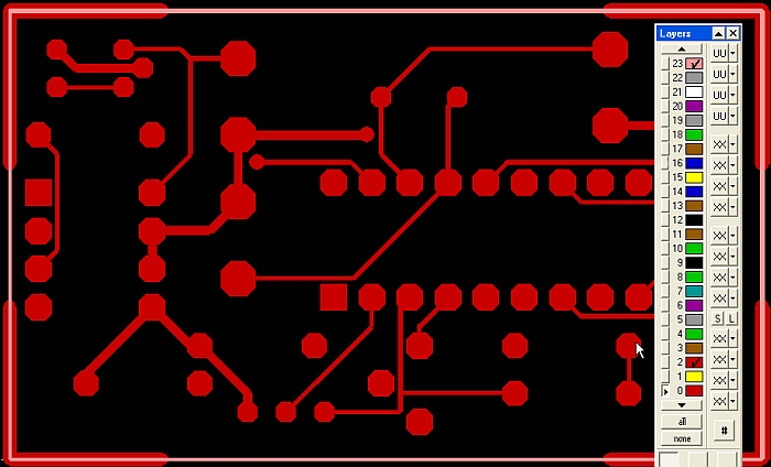
Then layer "2=Copper bottom":
Now see all of them together. Leave the aura around the pads, later you might create them as Thermal Pads if you wish.
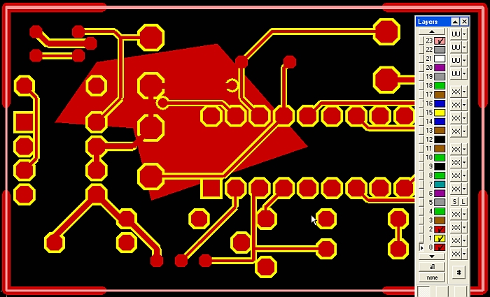
You can create an unlimited number of custom sized groundplanes upon one layer - all carrying different signals (eg. for separating analog and digital). The procedure is the same. You only need to assign different GND potentials to them, just the way you like...


