Coordinates
also see Origin, Snap Point
Entering element's coordinates manually
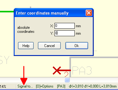
If you currently are creating elements like signal wires, tracks or housings or whatever, you may enter coordinates manually to a dialog. Open this dialog by pressing key [*] or [+].
Example: During the placement of a signal track the status bar shows: "Signal to..." and TARGET 3001! expects the definition of a coordinate. By clicking M1 you might neter the coordinate by mouse. If the coordinate does not fit to the grid you won't reach it by mouse. Now you press [*] or [+] and the dialog appears which allows entering the coordinates by numbers.
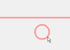
Guess you would have a PCB outline with several mounting drills given by a DXF import. Instead of placing the mounting drill holes at any spot in order to add the correct x- and y- coordinates afterwards, you might do it quicker. Use the dialog: "Enter coordinates manually" as well as it's additional functions. To get this dialog instead of a mouseclick you press the [+] key. Example: The following image shows part of a board outline from a DXF-Import having a predefined spot for a mounting drill hole:
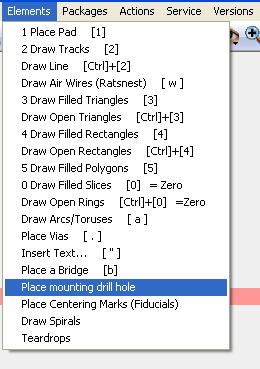
Now select option "Place mounting drill hole" in menu "Elements"
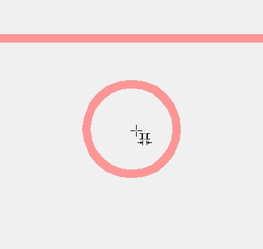
Now hover the cursor about middle of the desired spot...
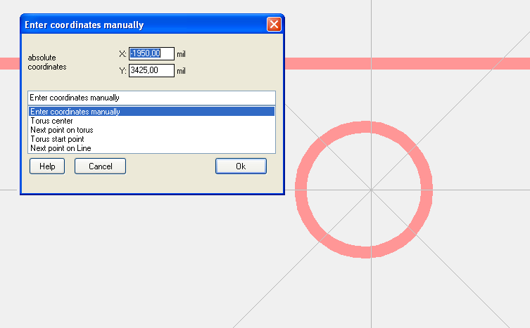
...and press keyboard key [+]. Immediately you will see a haircross centered to cursor position and a dialog "Enter coordinates manually" opens. You can do that in any mode with any element as a placement aid because sometimes elements are off the grid and you won't manage to hit a certain spot. Use this [+] function! Now you can enter the coordinates manually x and y. Or - and that's the hit - you might select a significant point of the object in question from the list:
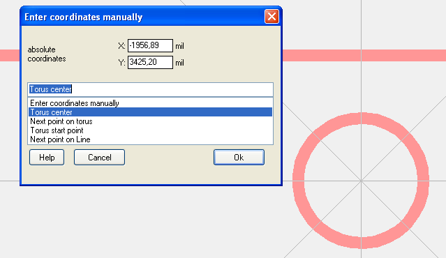
In our case we would choose "Torus center". The hair cross jumps exactly to this point:
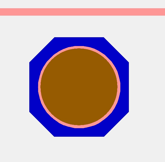
Now press Enter and the drill hole is placed correctly.
The principle is while being in a certain drawing mode you hover the mouse close to a certain spot of the desired element and click [+] in order to define the cursor's destination by significant parts of the object in question. Always when a mouse click is expected you can use the [+] function.
Now you should delete the initial circle so that it won't be milled as an outline but only drilled as a Mounting hole. for doing so press key [s] (for select) as long as the ring flashes. Now [Delete] it. The mounting hole itself you will be able to edit by a M11 on it and entering to the dialog "Change mounting drill hole".
Exact positioning, accurate placement
A user reports:
I need to place some components on the circuit board exactly e.g. left side of the capacitor must be positioned at a distance of 3 mm from the left edge of the board. In TARGET 3001! the positioning of a components works from the handle cross always, which is placed in the middle of the component usually. Now in order to calculate the position of the left edge I need to get the width of the component from the component data and divide by 2, which is error prone and time consuming. Would be a desirable option if I could pick a vertex/edge of the component to which the positioning of the component refers to.
Solution:
Select the component as a whole. Now hover the mouse near the left edge of your part. Now let the mouse be. Hands off! Now press the [+] key on the keyboard. A dialog opens and you can use the arrow keys on the keyboard (not the mouse!) in order to navigate. A proposal for a distinctive point of the component can be selected, or the option to enter the coordinates of a point on the component by hand. The crosshair shows exactly which point is meant. Press [Return] to close the dialog (hands off the mouse!). Now tap the keyboard button [d] for displace. Finally, you can touch the mouse again. Now the mouse catchpoint is positioned exactly at the desired spot of the component.
If you now want to come to rest with this point of the component on a certain other point, drag the componen close to this target point using the mouse. Do not click!. Now again press the [+] button. The dialog that we already know opens again. Select the desired option from the list by the use of the keyboard arrow keysor enter the coordinates manually. Press the [Enter] key. The selected point on the component snaps on the target coordinates.
If the edge of the component is on the grid, it's easier: select the component, hover the mouse on the edge and type [d]. Now displace the part on the grid using the arrow keys (mouse allowed as well).
In order to place a part exactly from the left edge of the board, you can use coordinates relative to the origin. Create a relative origin by pressing the [Home] or [Pos 1] key at cursor position. This relative origin can be caught by [+] as well. Go back to absolute coordinates by pressing [Home] or [Pos 1] twice.


