Snap Point
also see Coordinates
snap on a point not being on the grid
Use a Snap Point to couple elements which are neither placed on a certain nor on any grid point.
An example makes this clear:
Guess you have a closed torus (circle) e. g. imported from a DXF file and wish to place a soldering pad exactly to the middle of it. Unfortunately the center of the circle is placed at a point which can not be reached by your grid in use or a fraction of it. Even if you switch off the grid completely you will not hit the center exacly. Now the "Snap Point" mechanism helps.
Important note: For defining the snap point you need to be in "Drawing mode" or in "Pointer mode". If a mouseclick is expected you press key [+] instead of clicking. During this action the cursor needs to be close to the point of interest.
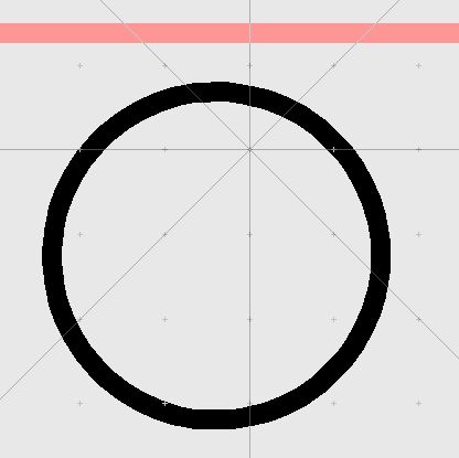
Image 1: In this example you have a closed torus (circle) whose center is not to be placed to a grid point.
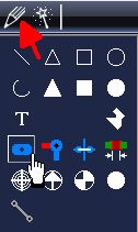
Image 2: Select option "Place Pad" from the drawing functions. Please note: Key [o] for Options allows the modification of the pad.
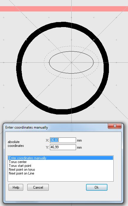
Image 3: The soldering pad moves like a phantom with the cursor. Now a mouseclick for placing the pad is expected. Instead press keyboard key [+] in order to open the desired dialog. Now you can select from various alternatives, e. g. "Enter coodinates manually".
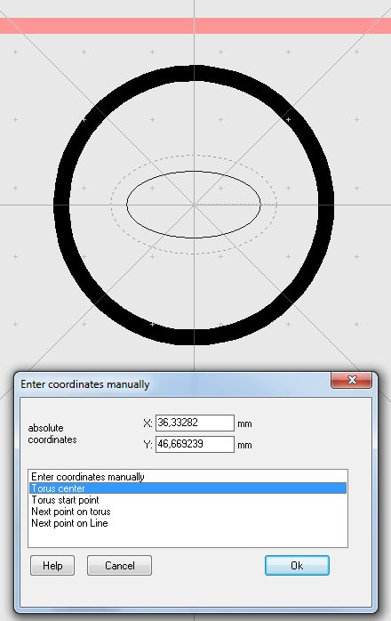
Image 4: Select the "Torus center", the phantom in the background moves to the desired spot. TARGET memorizes the last point caught by [+] within the grid (in most cases is such a point located off the grid). This point later can be accessed by the cursor.
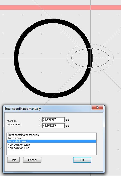
Image 5: Select the "Torus start point". This might be interesting with an open torus (arc).
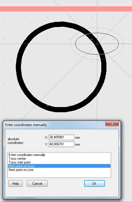
Image 6: Select the "Next point on torus", referring to the position the cursor had when launching the [+] key.
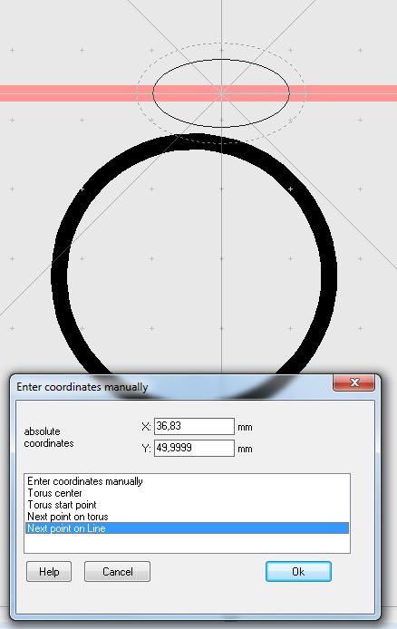
Image 7: "Next point on line" means any neighboured line element closest. Here it is the outline of the board.
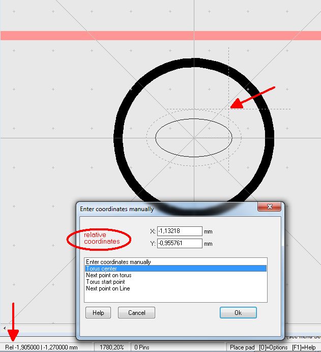
Image 8: You can work in a system of absolute coordinates or in a system of relative coordinates. A relative origin is created at cursor position by pressing key [Pos1] =(Home). Alternatively you can press [Ctrl]+[Pos1] in order to enter the coordinates of a relative orign manually. Pressing [Pos1] twice returns to absolute coordinates.
Place a certain point of an object exactly to a certain coordinate
Another situation for using this feature: After having imported a complex DXF PCB outline to TARGET 3001! you may wish to position a certain point of this figure to the absolute origin...
Snap on a certain point close to the cursor for measurement
Use function "Measure and dimensioning" from Menu "Actions". In the status bar it can be read "Measure from...". Now hover the mouse close to the starting point but don't click. Press keyboard key [+] instead. Now you can skip to points close to the cursor using the keyboard keys "Roll up", "Roll down". Press [Return] for OK.
With the target coordinate of the measurement you do the same: Hover the mouse close to it and press key [+]. Chose the exact coordinate and press [Return]. Now determine the position of the (measurement-) arrow and the text. Done.

