Color
Open this dialog by the use of the button ![]() You will find this button beneath
You will find this button beneath ![]() All colors which are independent from a layer number can be set here:
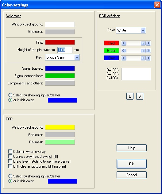
All colors which are independent from a layer number can be set here:

Image: The Color-settings dialog
Settings made here dominate the settings under which the project that you now might open was saved earlier. Exception: The layer colors (layout).
- Window background
- Grid -color
- Ratsnest
- Pins
- Busses
- Signal busses
- Colormix when overlay: A red- and a blue line on top of each other result in a violet line. This works the best with clean RGB-colors and a black PCB-background color or with mixed CMY-colors and a white PCB-background color. More then 256 colors should be possible with the graphic card driver.
- Outlines only: Only the outline of lines and areas will be displayed, the filling is ignored. The kind of presentation draws the contents of the current window much faster and it is possible to see structures inside of areas. Draw layer hatching twice: If you assigned a pattern to the layers in the layer dialog, these patterns will be drawn more dense. For easy toggling please use the hash key [#].
- Drillholes as pictograms: For a drilling plan, small symbols can be created for each drill hole diameter. This option is the reason why drillholes will not be printed as open drillholes. This has been several times an issue for the technical support. You must call first the function File / Input/Output Formats / "Drilling plan with pictograms". The call of this function automatically enables this feature (a cross will be set at the according field ). After you have printed the drilling plan, you should disable this feature again. If you forget this, small little triangles and stars will be printed on the black solder pads, therefore an open (white) drillhole will not be seen.
- Select by showing lighter/darker: Selected elements in PCB mode can be displayed either by using the same color but in a different intensity or by the use of a total different color. The first option has the advantage that it's possible to recognize the original colors. Option two is more clear in some cases. For example, it is not always easy to divide clearly the a dark light-green from a light dark-green on screen.
It is possible to adjust the related VGA-colors for each of the 16 colors directly through their RGB-value (red, green, blue). Therefore you can adapt the colors easily to the different display modes of the graphics card and the monitor. As an example, the intensity of individual colors can be influenced.
The button [S] saves the current color settings in a textfile which you later might load again using button [L].
The color of the air wires (ratsnest) in the layout can be set in the schematic view. Highlight a complete signal and press the key [e] for edition. In the flashing dialog please do the "color of air wires" setting.

