Package
Definition
In TARGET 3001! we call the pattern of the solder pads of a component for use in the PCB layout The package.
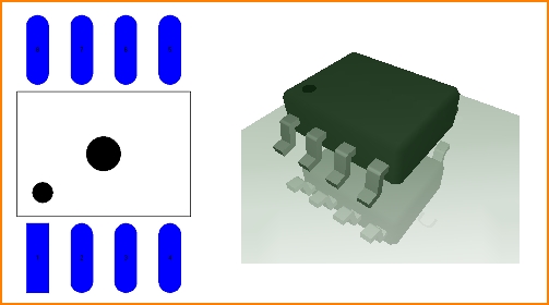
Image: On the left a a SO8 package. Right next to it its 3D-illustration.
This package can be used in TARGET by several components in the sense of a package proposal. Because a component in TARGET consists of a schematic symbol and the proposal of a suitable package for the layout. The package proposal adheres to the symbol. You can deviate from the proposed package and use a different package for each symbol.
Find a package
Packages have names. List of integrated circuit packaging types. Search in the TARGET component database in tab "Package" for the Package name, here for example so8 (case insensitive, blanks also):
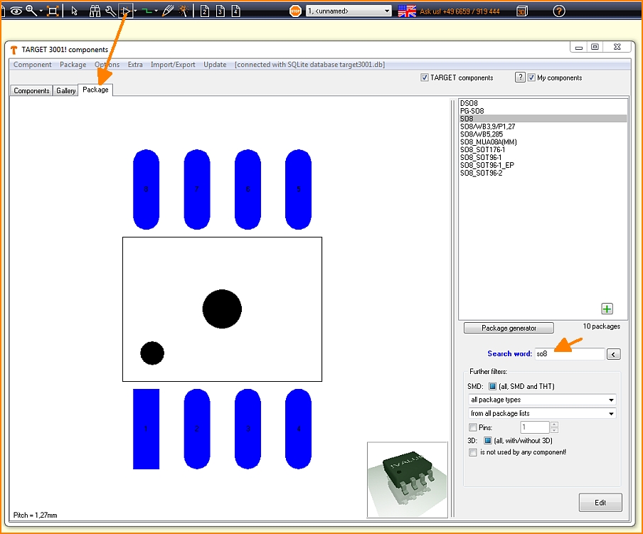
Image: The component browser tab "Package". Open the browser also by key [Ins] or [i].
Packages in whose name the letters so8 appear:
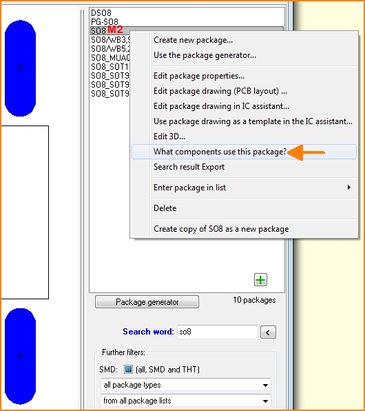
Image: What components propose this package? Right click M2 on the package name in the browser opens a context menu with a variety of options.
Change package
Package is still in the data base
If you want to change a package that is still in the database, click M2 - as above - to its name in the package browser. Or click M2 to its image in the component browser and select from the options of the context menu:
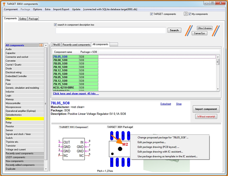
Image: Edit a package in the component browser (= data base)
Package already placed in layout
If you want to change a package that you have already placed in the layout and the changes should only refer to this project but not to the database, use the "Change package" dialog. It opens:
- on double-clicking on the handle cross of a housing
- by single-clicking on the handle cross of a housing and pressing the keyboard key [e] for edit. Then check the box at "Package" and press OK.
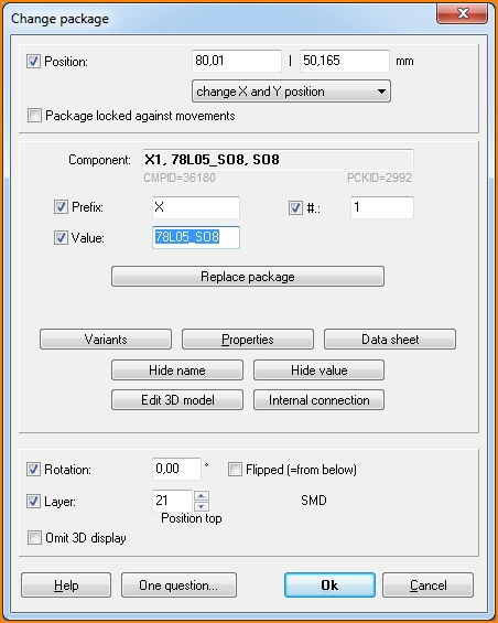
Position defines the coordinates of the handle cross of the package. X- and Y-value can be changed on one strike or only the X-value or only the Y-value, see drop down box. The package will be blocked against any movement if box is ticked.
The line Component contains name, value and Package proposal of the highlighted one. In this line no adjustments can be made. Only in the lines Prefix, Number # and Value. Prefix and number represent the name of a component.
The six buttons mean:
Variants - the maintenance of assembly variants (alternatives of assembly within the same project)
Properties - The list of properties of a component
Hide/Show name - Hide or show the component name (not the package name).
Hide/Show value - Hide or show the component value.
Note regarding earlier versions: Component name and -value can be faded in/out separately in the layout. Fading out by deleting from the layout. Fading in by: Highlighting the package in the layout, hovering the cursor to a place where name/value shall start. Starting the Text mode by pressing the ["] key. In the text dialog selecting Function "Component name" or "Component value".
Edit 3D model - self explanatory
Internal connection - Connections having internal load capacity can be derived from the schematic.
A Rotation of a package by degrees would not be defined within this dialog. Preferably it would be done using [Shift]+[t]. The entry here only shows a rotation which had been effected earlier.
The same with the entry Flipped (= from below) - it is only for announcing whether a part is assembled from the bottom side (box is ticked). No manipulation here - better done in menu: "Edit/Mirror"
The line Layer defines the layer on which the outline image of the package for position print appears. Normally it is layer 21, Position top. But also layer 7, Position bottom, is possible or any other reasonable layer of your choice.
Tick at Omit 3D display effects exactly this: No display of this package in the 3D view of the board.
Draw a new package
How to draw a package please find in the Edit component article.
See also Import Package
See also Export Package

