Rectangle
General
Rectangles can be filled ![]() or unfilled (open)
or unfilled (open) ![]() . Select the desired mode under the pen icon
. Select the desired mode under the pen icon ![]()
Filled rectangles
You can reach this mode...
by [4] or
by "Draw Filled Rectangle" in menu "Elements" or
by the tool ![]() under the pen icon.
under the pen icon.
What you can do...
Press [o] (for options) to enter rectangle settings. When the rectangle is started with M1, move the mouse diagonally to open a rectangle. With another M1 you can finish the rectangle. Existing rectangles, which are not rotated by angles other than 90° can be dragged on their tips with the dragging function [g] or after highlighting a line with M1H on a little black box.
Leave this mode...
by [ESC] or M12
Open rectangles
You can reach this mode...
by [Ctrl]+[4] or
by "Draw Open Rectangle" in menu "Elements" or
by the tool ![]()
What you can do...
Press [o] (for options) to do line settings. When the rectangle is started with M1, move the mouse diagonal to open a rectangle. With a M1 click you can finish the rectangle. Existing open rectangles can be dragged on their tips with the dragging function [g] or after highlighting a line with M1H on a little black box.
Leave this mode...
by [ESC] or M12
Change rectangles
a filled rectangle can be dragged to shape by its corners as long it hasn't been turned by 'unusual angles. The following dialogs you'll receive if you double click on a filled rectangle:
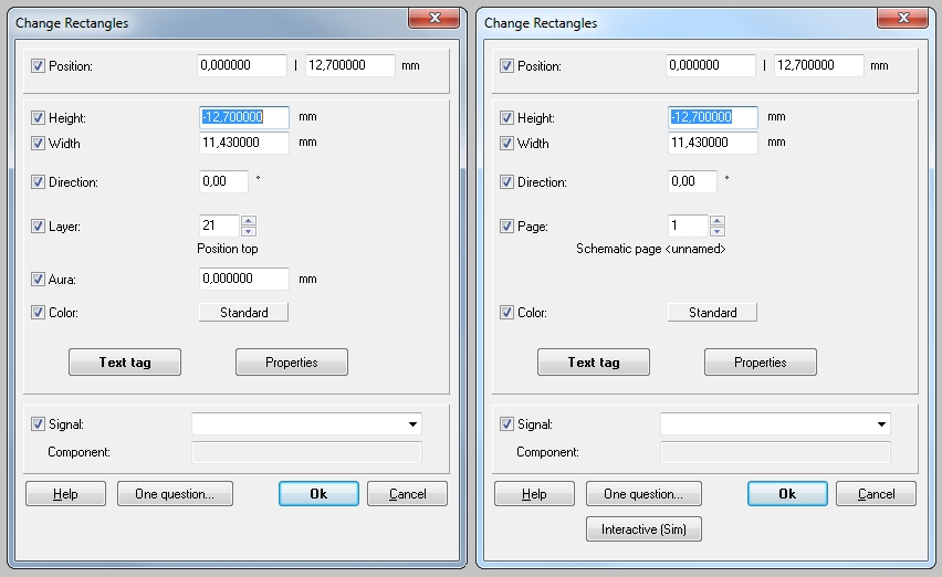
Image: The dialog "Change rectangles" in schematic and layout view
Enter width, height in mm and orientation in degree°. If in schematic, enter the schematic page where the rectangle shall appear. If in layout, enter the layer. Assign a signal to it if needed. What is the meaning of those checkboxes in front of properties?
An "open rectangle" gives the dialog: "Rectangle of 4 lines". An open rectangle can not be equipped with a signal.
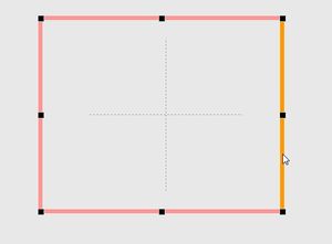
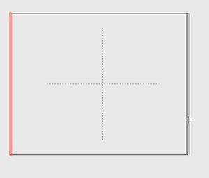
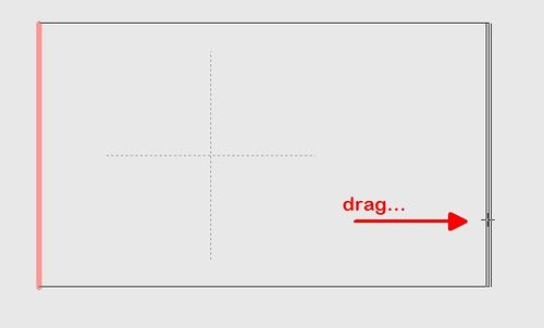
Drag line orthogonally
Have a look at the sidebar and release this button:
The effect is that you can touch single parts of a drawing, like a line for example. Now touch the line you desire to move orthogonally, hold it with the mouse and drag it into position.
Image
Image
Image
Edit dimensions
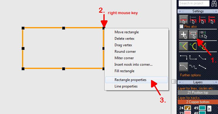
Have a look at the sidebar and activate this button (1.):
It will make the whole figure highlighted if you just hit only a line of it. Now after the rectangle is highlighted completely please click one of the black vertices with a right mouse click in order to open its context menu (2.):
From the flashing context menu select entry: "Rectangle properties". What you get is a box to enter the width and hight in decimals:
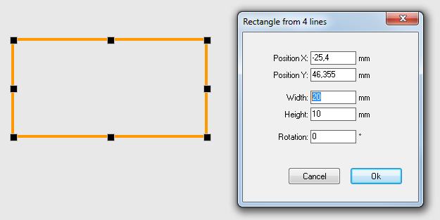
Image: enter width and height to the dialog.
Alternative: Release the above mentioned button. Hover the mouse to one of the corners of the rectangle. Press the [Pos 1] key (it is the "Home" key) in order to place a relative zero to this spot. Now double click a single line and enter the coordinates of its start and end point using the relative origin. It makes the coordinates start from zero at this point
For getting back to absolute coordinates, press the home key twice.
Positioning of a rectangle
No matter if you move in relative or absolute coordinates - it can be defined to which coordinates the center or the bottom left corner of the rectangle shall be positioned. In the following image a relative origin was placed by the use of the [Home] key =[Pos1] key, see the little cross in hatched line. Now you move in relative coordinates. The coordinates in the rectangle dialog refer to it, to be recognised by the little red hint rel. in front of the coordinate boxes. So first you define the coordinates (rel. or abs.) of a point somewhere on the canvas. Then you define which point of the rectangle (center or bottom left corner) shall be placed there.
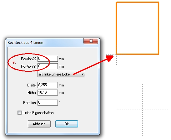
Image: The bottom left corner of the rectangle is placed to rel. 0|0
Besides: Return to absolute coordinates by pressing the [Home] key twice. The little hatched cross will vanish.
Round corner
Corners of open rectangles can be rounded by the use of the drawing context menu. Highlight a line and click M2 upon a touchpad:
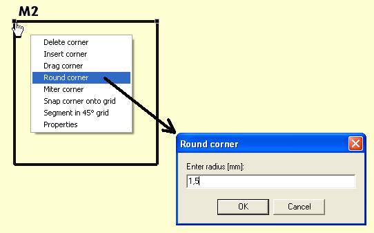
The result can later be undone by a M1 click od the bending and a M2 click on one of the touchpads of the bending:
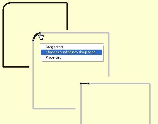
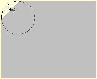
A filled rectangle can not be treated this way. If you want a rounded corner, please draw a polygon and add a circle:
Outer corners right-angled (not rounded)
If you delete the property "Rounded" from the lines that make up a rectangle (by removing the check mark in the dialog box), something like this will appear:
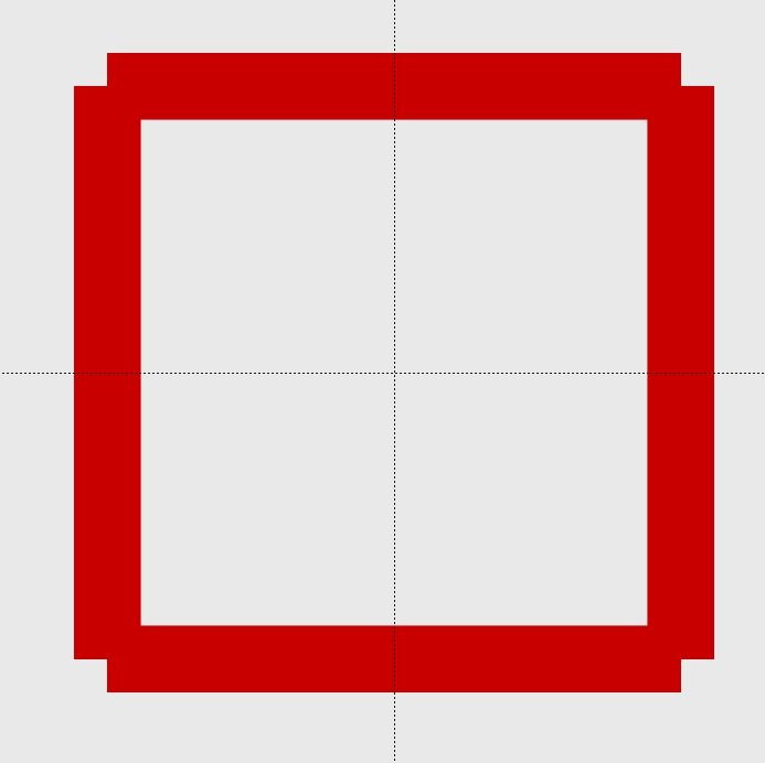
Image: Rectangle made of lines whose ends are not rounded.
A piece is missing at the outer corners, exactly half the line width. How to get the corners closed at right angles?
Solution: Extend the two vertical lines by half the line width to the north and south.
Select a line, and press keyboard key [e] for edit:
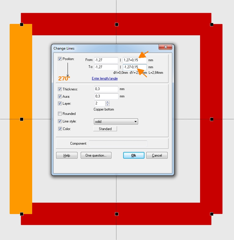
Image: Extend the Y-coordinates of the line "From To" by 0.15 (= half line width) to north and south.
Simply enter +0.15 or -0.15 in the boxes next to the Y coordinates (first and second lines of the dialog box). The fields can calculate. The small arrow in the top left corner of the dialog box at "Position" indicates what exactly "From-To" means in respect to the coordinates. This also determines in which line plus or minus is to be calculated.
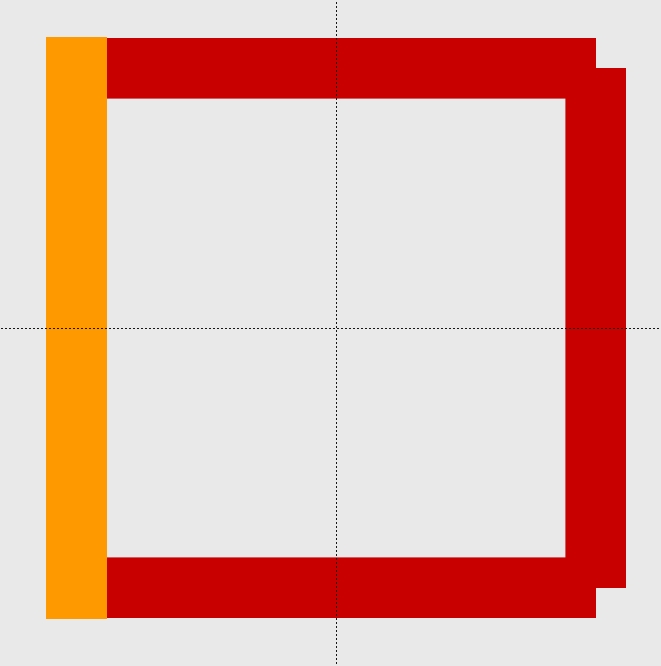
Image: The result for this line would look like this. Do the same at the right vertical line.
Result:
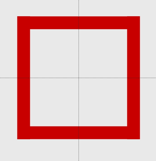
Image: Rectangle with 90° outside corners.


