Difference between revisions of "Create a new component"
| Line 19: | Line 19: | ||
<br><br>Create an individual symbol by the use of the '''Symbol-Generator''': | <br><br>Create an individual symbol by the use of the '''Symbol-Generator''': | ||
| − | <br><br>[[Image:SymbGenerator_e.jpg|Symbol Generator|Symbol Generator]]<br>Image 5: The symbol generator creates a basic structure of a symbol. <br><br>In this case it has 14 pins made of four sub symbols (three by four pins plus two). The first sub symbol is shown here, the last one will be treated as a "rest" (see ticked box at "last symbol as rest". The tick at "Alphanumeric" | + | <br><br>[[Image:SymbGenerator_e.jpg|Symbol Generator|Symbol Generator]]<br>Image 5: The symbol generator creates a basic structure of a symbol. <br><br>In this case it has 14 pins made of four sub symbols (three by four pins plus two). The first sub symbol is shown here, the last one will be treated as a "rest" (see ticked box at "last symbol as rest". The tick at "Alphanumeric" places characters and ciphers instead of subsequent numbers. Like a matrix: A1, A2, ... B1, B2, ... <br><br>The field: "Arrangement" defines the suggestion for a positioning uf the overall number of pins at the new symbol. In our case the diesem Fall sitzen die Pins links.<br><br>Ergebnis der Einstellung gemäß obigen Dialogs: |
<br><br>[[Image:dreiGatterZweiPinsRest.jpg|Drei Gatter zwei Versorgungdanschlüsse als Rest|Ergebnis der obigen Einstellung]]<br>Image 6: Ein 14-pinniges Symbol mit insgesamt 4 Sub-Symbolen (vgl. Griffkreuze), wobei das Letzte als "[[Rest]]" behandelt wird.<br><br> | <br><br>[[Image:dreiGatterZweiPinsRest.jpg|Drei Gatter zwei Versorgungdanschlüsse als Rest|Ergebnis der obigen Einstellung]]<br>Image 6: Ein 14-pinniges Symbol mit insgesamt 4 Sub-Symbolen (vgl. Griffkreuze), wobei das Letzte als "[[Rest]]" behandelt wird.<br><br> | ||
Anschlussnamen mit der '''Textfunktion''' bearbeiten: | Anschlussnamen mit der '''Textfunktion''' bearbeiten: | ||
Revision as of 14:04, 13 May 2016
See: Schematic menu Compnents/Create a new component...
This area step by step guides you creating a new component. Already existing, similar components or its elements can be used. All automatic functions are offered during this process so that you most quickly will be able to use your desired part without unnecessary double work.
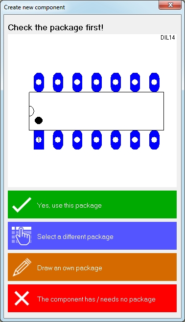
The opening dialog:
First decide which package (footprint pattern with package outline) you would like to use.
If you need to "Draw an own package" because you can not find a matching one among the existing, start with the magic wand in the opening dialog. Here use the assistants:
* Package Generator
* Derive package from existing package (you should know the package name!)
* Package via script
Only if you can not use an assistant you should start to draw an outline manually and place pads manually as well. How to do this best, please read here:
How to draw a package
Save the package afterwards to the data base using a suitable name and open menu item "Create a new component" again. Now click the blue panel "Select a different package" and select the one you just have drawn.
Continue top left with the magic wand in order to create a symbol:
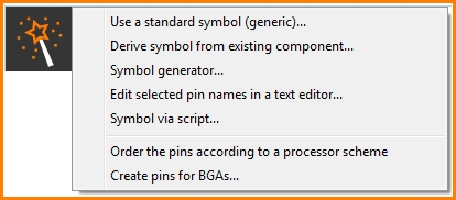
Image 2: The options of the magic wand when creating a schematic symbol.
Maybe a 'standard symbol (a generic) matches? Select one from the list.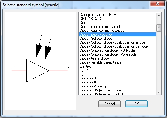
Image 3: Select a generic symbol.
Generic is just another word for "default" or "primitive". Maybe you need to check the Pin numbering of the generic symbol and synchronize them with the pad numbers of the package. For this reason a separate dialog will open. Pin number and pad number (cipher) need to be identical. It's just the same cipher of pin and pad which cares for their logical/electrical linkage.
Eventually you can derive a new symbol from an existing component. The idea is to copy a symbol of an existing component to your canvas in order to modify it independently from its source.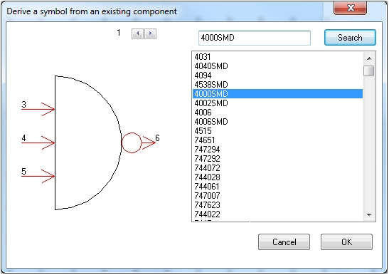
Image 4: Derive a symbol from an already existing component. Enter the component name to the search line. Now the symbol appears on the canvas and you can modify it as you please.
Create an individual symbol by the use of the Symbol-Generator:
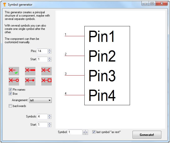
Image 5: The symbol generator creates a basic structure of a symbol.
In this case it has 14 pins made of four sub symbols (three by four pins plus two). The first sub symbol is shown here, the last one will be treated as a "rest" (see ticked box at "last symbol as rest". The tick at "Alphanumeric" places characters and ciphers instead of subsequent numbers. Like a matrix: A1, A2, ... B1, B2, ...
The field: "Arrangement" defines the suggestion for a positioning uf the overall number of pins at the new symbol. In our case the diesem Fall sitzen die Pins links.
Ergebnis der Einstellung gemäß obigen Dialogs:
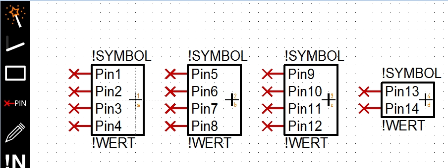
Image 6: Ein 14-pinniges Symbol mit insgesamt 4 Sub-Symbolen (vgl. Griffkreuze), wobei das Letzte als "Rest" behandelt wird.
Anschlussnamen mit der Textfunktion bearbeiten:
Anschlussnamen als Text bearbeiten.
Image 7: Markieren Sie Anschlüsse im Symbol, alle oder nur Teile daraus. Nehmen Sie die Anschlussnamen aus dem Datenblatt oder aus sonstiger digitaler Quelle in Ihre Zwischenablage und fügen Sie sie im Dialog ein. Bringen Sie sie in die korrekte Reihenfolge, Symbol erzeugen, fertig. Für Ball Grid Arrays (BGA), die einen Matrix-Aufbau haben, können auch alphanumerische Pin-Bezeichnungen in die Vorlage genommen werden. Dies erleichtert die Zuordnung der Anschlussnamen.
Verwendung des Symbol-Assistenten:
Der Symbol-Assistent
Image 8: Der Bauteil- und Symbolassistent
Beachten Sie bitte den folgenden Artikelzu diesem Aspekt:
Anschlüsse gemäß prozessor-Schema anordnen...
Erzeugen Sie ein Symbol wie ein BGA:
Symbol wie BGA
Image 9: Der Dialog BGA-Anschlüsse erzeugen.
Die Checkbox "geklappt" meint, dass Zeilen und Spaltenbenennung an der Diagonale gespiegelt werden. Zeile A wird zu Spalte A und umgekehrt. Die Checkbox "Z" erlaubt bedeutet: Der Buchstabe Z ähnelt einer 2, was zu Unsicherheiten bei der Benamung der Matrixfelder führen kann. Wenn Sie in der Benamung dennoch ein Z verwenden wollen, setzen Sie bitte den Haken ins Kästchen.


