Contour Autorouter
See layout "Menu Actions/Automatisms and assistants]]
The "Contour-Autorouter" is a fully gridless and grid-independent router. It places the track in the first run the way that this track would be the only one to be placed. Errors caused by crossings and distance violations are normal and almost desired. In the following runs, the errors get more and more "expensive" for the router and therefore grow more rare until a 100% resolution is hopefully reached. In the following "Optimizing" runs, the preferred directions are "forgotten" and the traces will be streamlined.
After several preparations the "Contour-Autorouter" begins to place the tracks, as distance- and crossing violations are allowed. The costs of these errors are increasing after several route-runs. At the end, no errors should be left. This logical statement insures that during the route-run of a single track, all other signals are noted. The management of the routing-area internally is completely vector-oriented and therefore independent of the memory from the grid (clearly contour-oriented). The route run can be stopped by pressing the [ESC] key.
The contour router is perfectly suited for larger projects with more subtle structures (for example: smd- or chip design) and layouts with several routing layers.
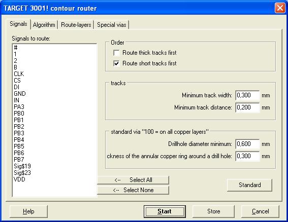
Select the signals to be routed on the left side.
You can define the order of the signals to be routed as follows:
Route large signal tracks first: Signals with a larger track-width will be routed before signals with a lower track-width.
Route short signal tracks first: Signals with a shorter ratsnest will be routed before signals with a larger ratsnest.
Minimum signal track-width: Please enter the minimum track-width here. The property MINIMUM WIDTH of a signal can overwrite this value:
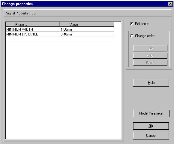
Minimum track-distance: Please enter a value for the minimum width here. The MINIMUM WIDTH property can overwrite this value.
Minimum drill-hole diameter: Please enter a value for the minimum drill-hole diameter of a standard via.
Minimum width of the annular restring of a drill-hole: Please enter a value for the minimum width of the annular restring of a drill-hole.
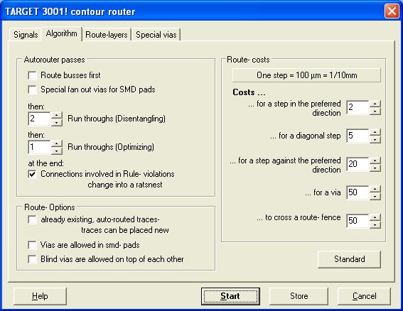
Autorouter passes:
Route buses first: This route-run is dedicated to bus- and memory structures.
Vias for SMD-pads: Smd-pads located on a preferred direction, will get a via to allow access to layers on an opposite preferred direction.
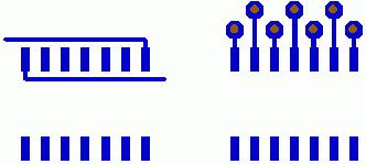
During the optimization stage, only these vias remain which will be used.
Run throughs (disentangling stage ): During the disentangling stage, all signal tracks will be placed independently of distance violations and crossings. These violations however will get more and more expensive after each run. Runsthroughs (optimization stage): During the optimization stage, no distance violations should appear. The preferred directions are ignored to reduce vias. All signal tracks will be straightened. Change connections involved in rule-violations back to ratsnest: Signal tracks, who cause distance violations or crossings (short circuits ) with other signals, will be cut at the end and displayed as unrouted ratsnest.
Route- Options:
Tracks which have already been routed from the Autorouter can be placed again: Please check, if tracks which have already been placed by the Autorouter can be opened and replaced again. Manually routed tracks remain unchanged. Allow vias in smd-pads: Activate this check box, if you want to do so. Allow blind vias on top of each other: Several vias of different signals can be placed on top of each other (for example: blind hole; blind via).
Route- Costs:
... for a step in the preferred direction: Each layer can have a preferred direction. The value entered here represents the costs for a step in the preferred direction.
... for a step diagonal: These are the costs for a diagonal step. The result is relative to the costs in the preferred direction.
... for a step against the preferred direction: These are the costs for a step against the preferred direction: The result is relative to the costs in the preferred direction.
... for a via: These are the costs for a standard via (=100). The result is relative to the costs in the preferred direction).
... to cross a routing-fence: These costs appear if a signal crosses a routing-fence. The result is relative to the costs in the preferred direction. Routing-fences can be of interest to distinguish between digital- and analog circuit blocks on the PCB or between circuit blocks with different voltage levels. A routing-fence is drawn as a line on the routing-fence layer. A layer with this function must be created.
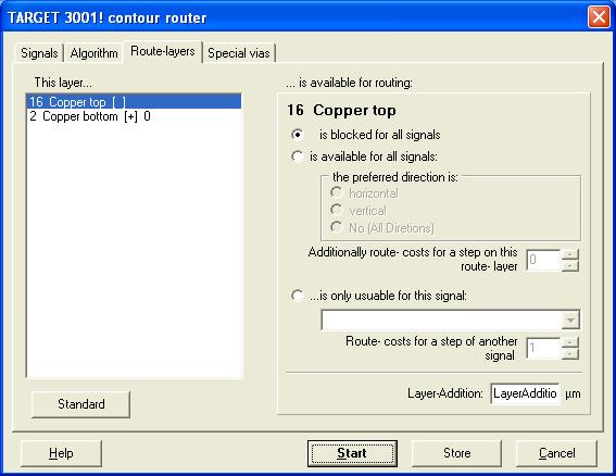
This layer ...
All layers capable to be routed will be listed here. Please select a layer to be edited here.
Route-layer:
... is blocked for all signals: This layer is prohibited for routing.
... is availabale for all signals: This layer can be used to route signals, but might have a preferred direction (horizontal, vertical, none). Additional routing-costs for a step on this route-layer: This is the result of the costs for a step on this layer. With this option, you can assign different costs for the individual layers. The result adds to the costs of the in the preferred direction.
... is only useable one signal: This layer can only be used for a given signal ( without preferred direction). To place another signal on this layer will cause extra costs, as shown in Routing-costs for a step of another signal.
Addition on this layer: Signals on this layer will be assigned to get an additional track width set by this value.
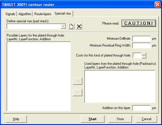
- Define special vias (Padstacks): here you can create or delete a special via as a padstack.
- Possible layers for the via: Layers displayed here, will not be used from the via.
- Layers used from the via (Padstack): Layers displayed here, will be used from the via.
- Minimum drill-hole diameter: Please set the value of the minimum drill-hole diameter for a via here.
- Minimum annular ring: Please set the value for the minimum annular ring for a drill-hole of a via here.
- Costs for a via: These are the costs for a via of this kind. The result is relative to the costs in the preferred direction.
- Addition on this layer: The output of the pad in the marked layer should be ....larger or smaller (-) as the original pad.

