Bill of Material BOM
General
See Menu "File"/Input/Output Formats/File transfer/Documentation/"Output Bill of Material"
The Bill of Material (BoM) is a text file listing the parts you have used in the layout. It shows line by line the properties you had chosen earlier from an editing dialog. IMPORTANT: A BoM can only be generated, if the component packages are placed within an outline of a PCB layout. In other words: No BoM without a layout.
The parameters of the Bill of Material (BoM)
The bill of material (BoM) is created as a text file with entries line by line. TARGET 3001! first gathers all properties of the components used to a list which you see in the dialog. Now tick the boxes of the properties you'd like to mention in your BoM (e. g. item number, manufacturer, distributor...)
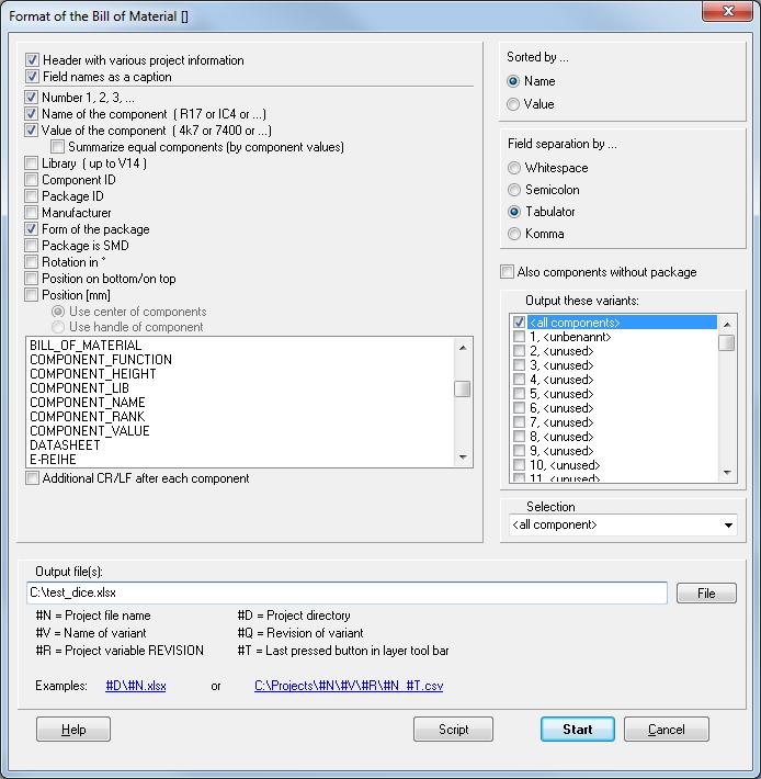
In contrast to the entries from "Number 1,2,3" to "Value" the other fields have an entry only if the corresponding property is established as such. The entries "Rotation in °", "Position on bottom /on top", "Position [mm]" are meant for automatic assembly only. The position in mm represents the coordinates of the packages' handle cross. The BoM will be created as a text file *.stk (alternatively *.csv or *.xls). It will be read line by line and can be interpreted by a normal text editor.
If you have variants of assembly with one project, you maybe like to create BoMs referring to each of the variant. Use the following syntax:
#V = Name of the variant
#T = The button pushed latest in the layer toolbar
#R = The project variable REVISION
#N = Project file name
#D = Project directory
For the fact that you might have several variants you may consider to give the BoMs separate file names. For this reason use button "File" do decide where to save and how to name.
BoM script
You can define and save a specific bill of material design as a script or share it with colleagues.
Please look here: BOM_script_format
The list of the BoM
The following example is made from the project dice.T3001 using the default settings:
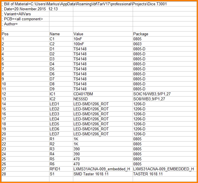
Entries like "Part number" or "Price" will only be available in the BoM, if data have been entered to the corresponding "Component property"-line.
From version 19: At the end of the BoM's header all Project variables begining with "BOM-" can be listed. Example: The project variable BOM-SPECIAL_INFO showing value 1234 would appear in the header like this:
;SPECIAL_INFO=1234
Also the author shown in the header will be defined out of the project variable "AUTHOR".
Example:
As Project variables the following properties are established:
AUTHOR with value: Markus, BOM-STORAGE_LOCATION with value: BIN_21, BOM-PRODUCT_LINE with value: TESTING and BOM-PERSON_IN_CHARGE with value JOHN SMITH, see image:
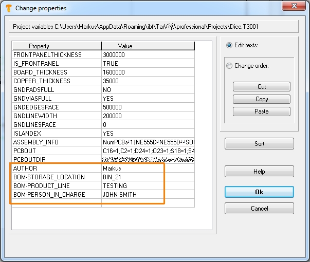
Image: New project variables get established by just writing into an empty line, also see a bit further down. To the left please enter the property, to the right please enter the value. In our case it is the AUTHOR as well as -focussing to an BOM appearance- the variables beginning with BOM-
The result in the BOM looks like this:
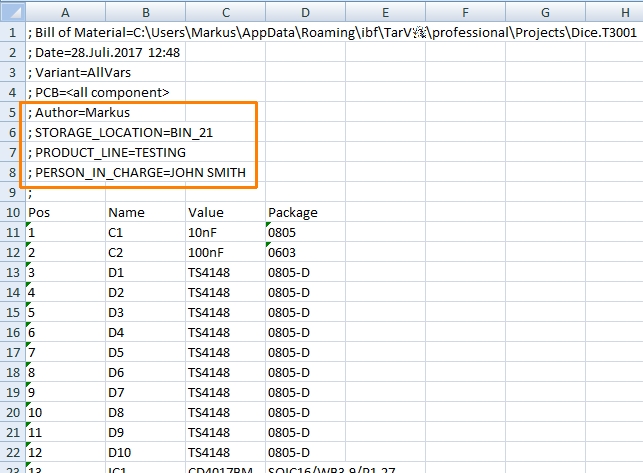
Image:Excerpt of the BOM, showing the mentioned project variables as BOM entries.
Create a new property to be listed in the BoM
By a mouse click M11 on the handle of a schematic symbol the dialog "Change Symbols" opens. Click M1 on the "Properties" button in order to define the properties of the component based on a list, see image. You alternatively can do it by the database browser properties management. If the component property BILL_OF_MATERIAL shows NO the part won't be listed in the BOM. Write this property in the way shown directly to the list of properties by hand. In the following example this entry does not appear so this part would be listed in the BOM.
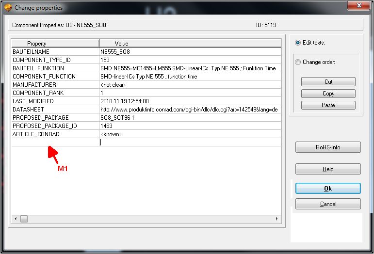
Image: The dialog "Change properties"
A click M11 to the empty line at the bottom of the list (arrow) allows the establishing of new and individual properties which later can be listed in the BoM. After all properties of a part have been entered, select menu File/Input/Output Formats/File transfer/Documentation/"Bill of Material". Component ID, Package ID and manufacturer can be listed as well. TARGET 3001! generates a list of all parts placed in the layout in Excel=® format (*.xlsx) or in in a text format (*.stk).
Only some parts of the schematic in the BoM
Maybe you would like to have only some parts of your schematic be part of the BoM. Maybe thoseof a certein schematic page. As mentioned above only parts being placed in the layout can become part of the BoM. That means what you get in the BoM is defined by what you have placed in the layout.
You could create modules to select the components you want: Select all components on a schematic page and use menu point "Group as a module" (see menu on image 1). Give the module a meaningful name and then select it in the BoM dialog:
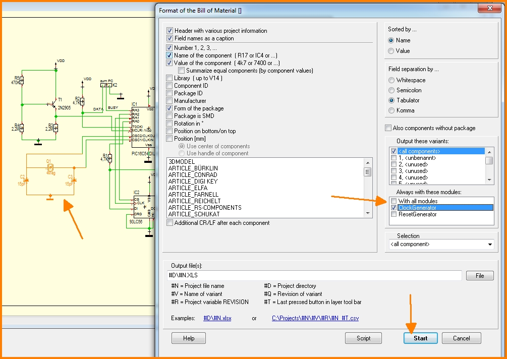
Image: Select a certain module in the BoM.
Another idea is to use the autoplacer when the layout is empty: It allows the placement of parts only of a certain schematic page. See layout menu Actions/Launch Autoplacer. Now create the BoM.
Summarize equal components (by component values)
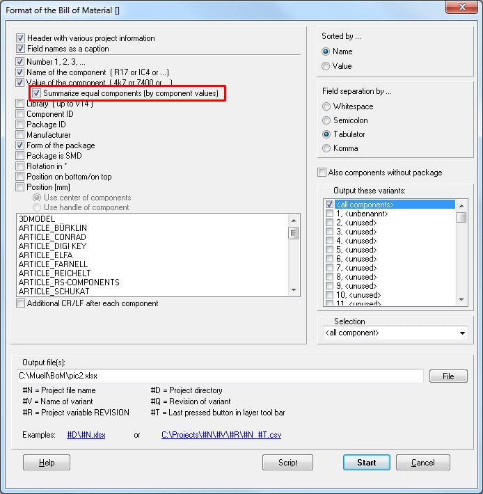
Image: The menu item Summarize equal components (by component values).
Equal components (by component values) are summarized only if the following component parameters are identical in the project:
- Component value
- Prefix
- The component property USED_PACKAGE
- The component property COMPONENT_NAME
From October 2018, components are only summarized, if the properties clicked in the list box are also identical.

