3D Syntax
Find a PDF summary here: http://server.ibfriedrich.com/download/pdf/en/3D_Syntax_e.pdf
General
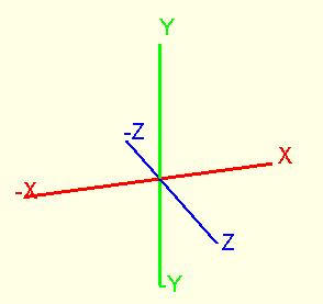
Coordinates (distances) are shown in mm, decimal separation by a dot. At top view upon the PCB: X (red) is the abscisse, it points positiv to the east, negative to the west. Y (green) is the ordinate, it points positive to the north, negative to the south. Z (blue) points positiv up to the spectator, negative down, orthographically to the X/Y area. NOTE: If you later want to rotate your model by the Z-axis, please add the [Ctrl] key.
The coordinate system (slightly turned):
Example:
0,0,0 is located in the origin.
0,0,0.5 is located 0,5mm upon the origin in positive direction of the Z-axis
Angles are defined in degree 0.0 ... 360.0, decimal separation by a dot. In the PCB area a positive angle tends from X axis to Y axis. Orthographically from the X axis to the Z axis or from the Y axix to the Z axis.
Example:
0,90
90.0,180.0
Colors are defined as a 3-Byte hexadecimal RGB-value.
Example:
$FFFFFF white
$0000FF red
$00FF00 green
$FF0000 blue
The syntax concerning one field (=body, =element) is written in one endless line. The syntax for a new element starts with a new line (thus new line = new field). TAB and CR/LF are overread/ignored. All entries of a solid which are placed after the "Chamferradius" entries are seen as a comment and do not have influence on the model. All entries of all other fields, placed after the "Color" entries are seen as a comment and do not have influence on the model.
The following elements are defined:
Solid (S)
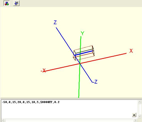
Hight and width are nothing else than a widening of a line in space, which itself is defined by the point (X1|Y1|Z1) to point (X2|Y2|Z2). The width is parallel to area X-Y. The edges of the solid are chamfered by the chamferradius. In the special case that the middle line points directly to z direction, the width is placed in X direction. By the way - a hyphen (-) in front of the S makes the solid a wireframe graphics, which sometimes eases imagination. The middle line is shown in blue. Viewing the wireframe graphics you might recognise that the "champfers" in reality are tapers. But the lighting generates the impression of a round edge.
Syntax of a solid: SX1,Y1,Z1,X2,Y2,Z2,Width,Height,Color,Chamferradius.
Example:-S0,0,15,20,0,15,10,5,$0000FF,0.2 (Taking away the "-" in front of the S makes the image solid!)
Torus (T)
A torus is a ring or a segment of it. It emerges by the rotation of a circle around an axis.
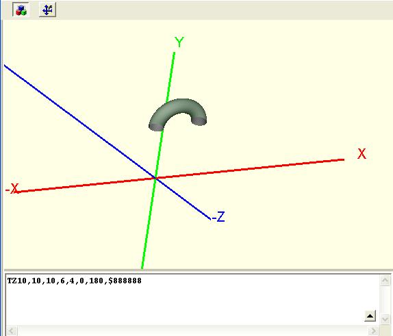
When a torus is defined as a TZ, the rotation axis is parallel to the Z axis. Pm means the center, Radius means the radius of the circle. Thickness means the diameter of a circle which gets a tube by rotation (coating).
Syntax of a TZ Torus:TZXm,Ym,Zm,Radius,Thickness,StartAngle,EndAngle,Color
Example: TZ10,10,10,6,4,0,180,$888888
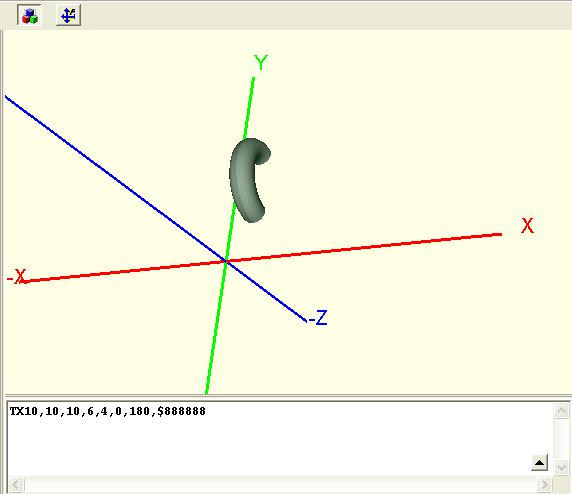
When a torus is defined as a TX, it has a rotation axis which is parallel to the X axis. Pm is the center, Radius means the radius of the bow, Thickness means the diameter of the coating:
Syntax of a TX Torus: TXXm,Ym,Zm,Radius,Thickness,StartAngle,EndAngle,Color
Example: TX10,10,10,6,4,0,180,$888888
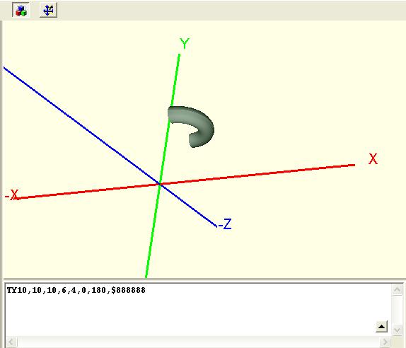
When a torus is defined as a TY it has a rotation axis which is parallel to the Y axis. Pm is the center, Radius means the radius of the bow, Thickness means the diameter of the coating:
Syntax of a TY Torus: TYXm,Ym,Zm,Radius,Thickness,StartAngle,EndAngle,Color
Example: TY10,10,10,6,4,0,180,$888888
Sphere (special form of a torus)
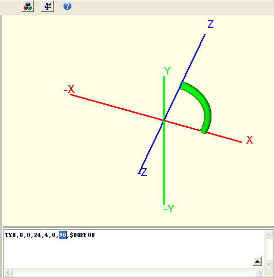
A sphere is constructed as a torus having a radius =0. At first select the primitive of a torus from the list. The following image appears after a slight mouse movement (M1H displace slightly in image):
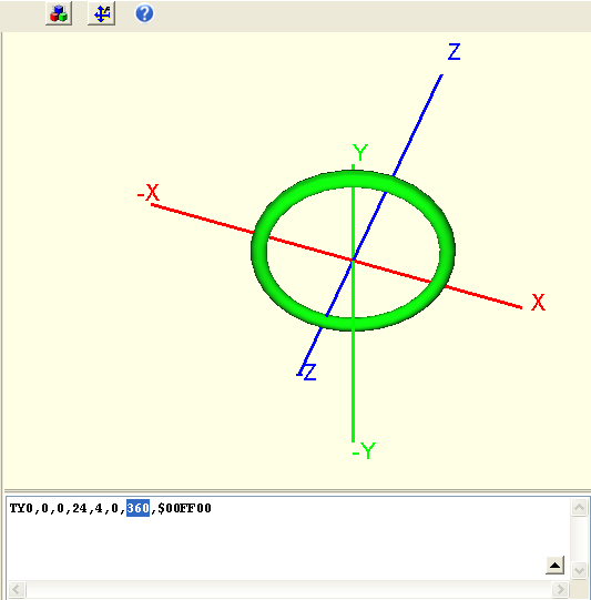
We see a torus as a quarter circle. If we expand the degrees from 90 to 360 we receive a closed ring having a radius of 24 mm and a tube width (thickness) of 4mm:
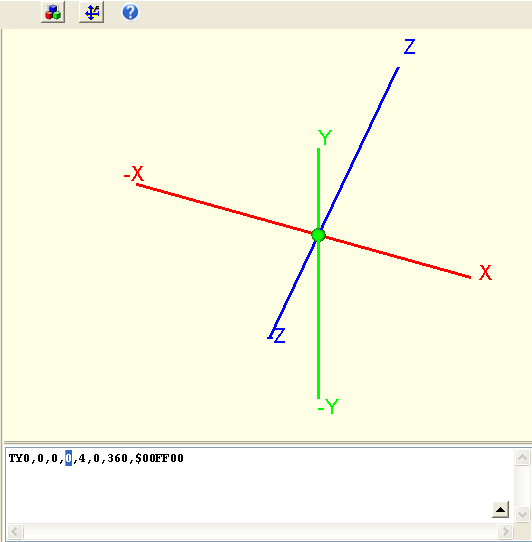
Now we simply set the radius from 24 to 0 and so receive a sphere with diameter 4mm:
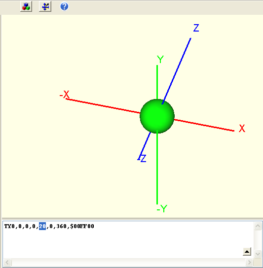
In order to manipulate the diameter of the sphere we have to set the thickness of the tube (=diameter). Enter instead of 4 a 20, so we get a sphere with a diameter of 20 mm:
Cylinder (C)
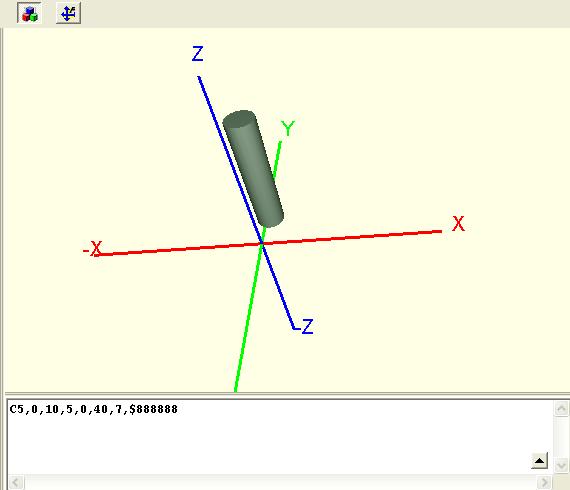
...means a cylinder with caps. P1 is the starting point, P2 is the end point. Thickness means the diameter of the coating.
Syntax of a cylinder: CX1,Y1,Z1,X2,Y2,Z2,Thickness,Color,Chamferradius
Example: C5,0,10,5,0,40,7,$888888,0
A cylinder can have chamfered edges:
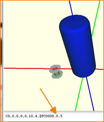
The chamferradius please enter after a comma behind the color (see arrow).
RESISTORCylinder (RC), color codes of a resistor
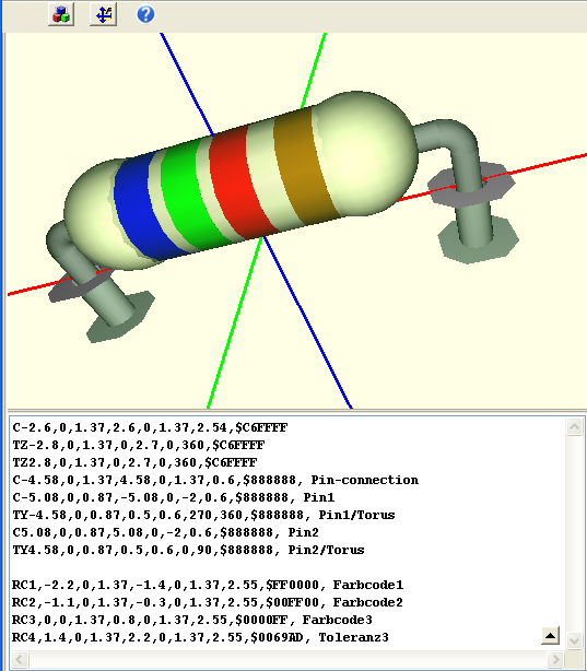
... with caps. The first three coordinates XYZ determine the first color code ring, beginning left. P1 is the point where it starts, P2 the end point. Width means the diameter of the tube ("wire").
Syntax:
RC1,X1,Y1,Z1,X2,Y2,Z2,width,color,comment
RC2,X1,Y1,Z1,X2,Y2,Z2,width,color,comment
Example:
RC1,-2.2,0,1.37,-1.4,0,1.37,2.55,$FF0000,color code 1
RC2,-1.1,0,1.37,-0.3,0,1.37,2.55,$00FF00,color code 2
RC3,0,0,1.37,0.8,0,1.37,2.55,$0000FF,color code 2
RC4,1.4,0,1.37,2.2,0,1.37,2.55,$0069AD,tolerance3
Extruded Polygon (E)
...starts always in X-Y area and gets extruded. N is the number of polygon tips. If the firs and the last point have different coordinates, the polygon gets closed. Z means the lower starting height, H means the resulting height of the polygon. H means hight in the sense of thickness of the whole body
Syntax of a polygon: EN,X1,Y1,,X2,Y2,X3,Y3,...,Z,H,Color
Example: E5,9,35,4,7,-14,10,-14,20,-8,13,0,3,$FF0000
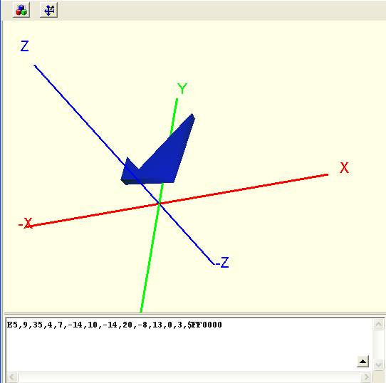
Image: Extruded polygon (outline brought to hight)
If the 3D representation consists of exactly one extruded polygon, then its hight value H automatically will be adopted as the value of the COMPONENT-HIGHT property. If there are further 3D elements, then the height is not automatically taken over.
Text (TT or Text)
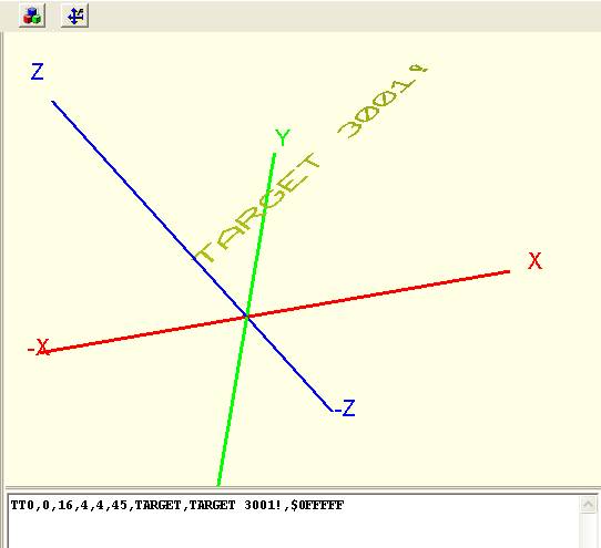
... is placed always parallel to the surface. Height defines its character height, Width defines it's width. Angle means the angle in area X-Y. Basis is bottom left of the first character. The common variables !Component (=component name), !Value (=component value), !Symbol (=name of the first symbol in Contents) are processed accordingly. You also might use a static text by typing it directly into the syntax line.
Syntax of a Text: TTX,Y,Z,Height,Width,Angle,FontType,Contents,Color
Example: TT0,0,16,4,4,45,TARGET,TARGET 3001!,$0FFFFF
STEP File
How to embed a STEP file:
Syntax: HashSTL,XHashStep,A1,B1,C1,D1,A2,B2,C2,D2,A3,B3,C3,D3,A4,B4,C4,D4,Color
Example: X-12345678,87654321,1,0,0,0,0,1,0,0,0,0,1,0,0,0,0,1,$0FFFFF
The sequence starts with "X" and is followed by two internal hash values for data container in the project. Those will automatically be generated as soon as you load a STEP file. A1 ... D4 is a 4x4 rotation- and translation matrix. At the end the color is defined. If you enter color $000000 (black), then the eventually existing color of the STEP model which you just have read in will be used.


