3D View
TARGET 3001! allows to inspect your layouts in 3D View. Fly through your TARGET-Layout and inspect the layout elements from all sides. By the use of the STEP 3D export you will be able to print your "assembled" board physically in 3D prior to real assembly.
To see what you have created, click in layout menu "View" on "3D view" or simply click button:

3D in general
3D Syntax
Creation of a 3D model
Modification of a 3D model
IDF Export
Precondition is, that a component has a 3D-model. Most packages in TARGET 3001! are furnished with 3D models.
Minimum requirements for 3D view
For a 3D representation of a component the properties at least need a height information (COMPONENT_HEIGHT). This simply pulls the floor plan upwards (extrudes it) so that a solid is created. We also call this an "extruded polygon". All components in TARGET by default have a minimum height of two millimetres, unless they already have the correct height according to the data sheet. Even if you want to add a 3D model to a component, you will first be asked if you want to create a simple "extruded polygon":
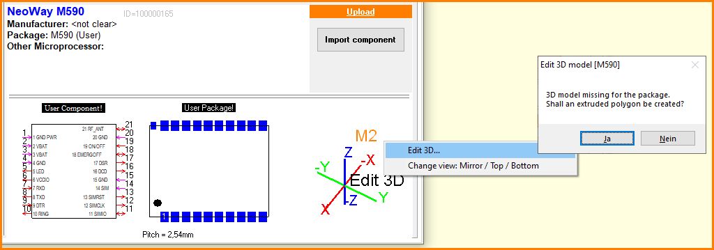
Image: Right click M2 on the area of the 3D image gives opportunity to edit the 3D Model. First you get asked whether you'd like to have a simple extruded polygon created. If you say yes, the following image shows what you will get:
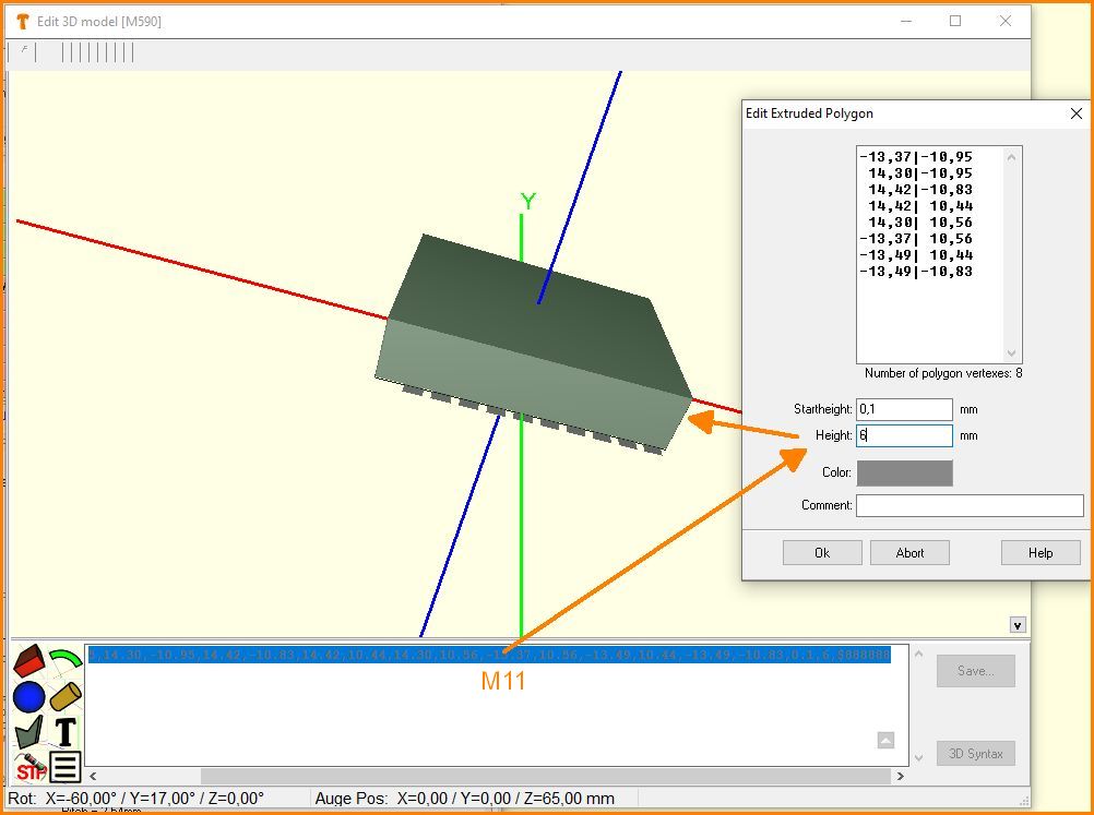
Image: Extruded polygon. Double click on the line defines the height of the extrusion.
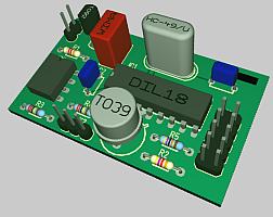
The following images will give an impression on the usability of the 3D function in TARGET 3001!:
The layout: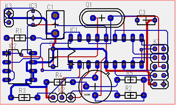 |
The 3D-View;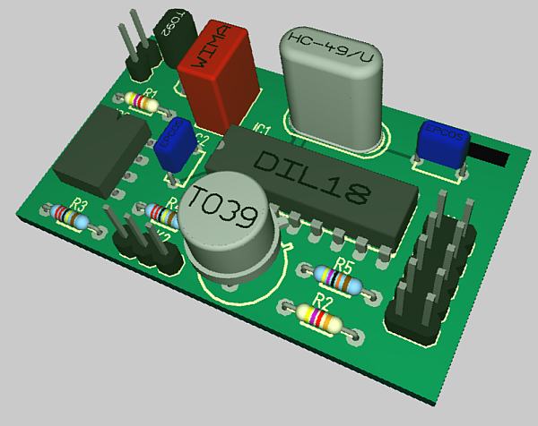 |
The 3D window
After the above-mentioned 3D-button is pressed, the following dialogue window opens. It grants various variants of the view:

Image: M2 means right click in free space to open a context menu
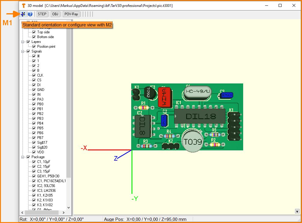
Image: M1 means left click on button: Standard orientation (central position) of the image.
M2 on the button enables alignment of the 3D-view by hand
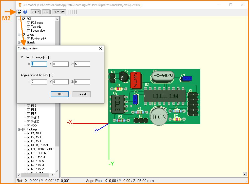
Image: Adjust zoom distance or rotation in space by hand.
In the column to the left check boxes to show or hide individual signals, packages etc. You also might highlight them in color. Components being switched invisible will also be omitted from the STEP output.
The Buttons in the top line allow an export to the formats STEP, OBJ and POV-Ray.
Create a 3D print
You can print your PCB (as a dummy) before the actual production with a 3D printer, assembled or unassembled. 3D data can be imported and exported in STEP format. A transfer of your TARGET project in *.idf is possible as well. Furthermore, the OBJ format and the PovRay format are available.
 |
Export to 3D format STEP Export to 3D format IDF | 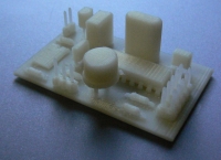 Plastic 3D dummy in FDM technique |
Precondition is that each component has a 3D model. You can very easily assign 3D models you have created yourself to your components. You will find step-by-step instructions in the articles mentioned above. If you want to create a new package with a 3D model quickly, the Package generator is suitable.
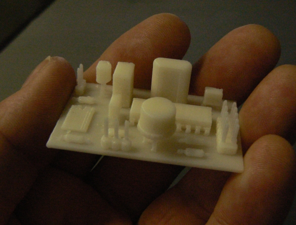 Image: A 3D print of the above project. How much is it?? |


