Symbol assistant: Difference between revisions
| (15 intermediate revisions by one other user not shown) | |||
| Line 1: | Line 1: | ||
== Introduction == | == Introduction == | ||
Find the symbol assistant in [[Menu Components]] / | Find the symbol assistant in '''[[Menu Components]] /Component- and symbol wizard'''. It is suitable for drawing ICs, with a large number of connection pins or also BGAs. The assistant works text-based. With the help of a script (= text-based form for instruction) we define the properties of any pin at any side of the symbol. This is much easier than it sounds. | ||
| Line 7: | Line 8: | ||
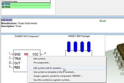
If you want to edit an existing component using this assistant or you might like to derive an new component from an existing one, please open the component browser using functional key [F2]. Search the part and click [[M2]] on it in order to open the context menu. | If you want to edit an existing component using this assistant or you might like to derive an new component from an existing one, please open the component browser using functional key [F2]. Search the part and click [[M2]] on it in order to open the context menu.<br><br><br> | ||
[[Image:edit_IC_assistant.jpg|400px|Click M2 on symbol or package to open context menu]]<br><br> | |||
Select option '''"Edit symbol with IC assistant..."''' or "Edit package with IC assistant..." or "Edit 3D...".<br><br> | |||
== The symbols and their pins == | == The symbols and their pins == | ||
| Line 15: | Line 18: | ||
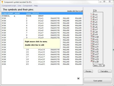
After click on the function mentioned in the Introduction the following dialog appears:<br><br> | After click on the function mentioned in the Introduction the following dialog appears:<br><br> | ||
[[image:e_bautsymbassi00.jpg| | [[image:e_bautsymbassi00.jpg|400px]]<br><br> | ||
The area beneath the header '''The symbols and their pins:''' will contain the text of the component script line by line. Currently it is empty. The menu '''Component script''' allows | The area beneath the header '''The symbols and their pins:''' will contain the text of the component script line by line. Currently it is empty. The menu '''Component script''' allows | ||
| Line 27: | Line 30: | ||
Bottom right of the dialog please find the button for generation of the component symbol after completion of the script. | Bottom right of the dialog please find the button for generation of the component symbol after completion of the script. | ||
Now we want to create the symbol of the Atmel 8-bit AVR microcontroller AT90S2313 with the help of the assistant. The appropriate data sheet we get from:<br>http:// | Now we want to create the symbol of the Atmel 8-bit AVR microcontroller AT90S2313 with the help of the assistant. The appropriate data sheet we get from:<br> | ||
[http://server.ibfriedrich.com/download/pdf/AT90S2313datasheet.pdf AT90S2313datasheet.pdf]<br><br> | |||
== Pin configuration == | == Pin configuration == | ||
| Line 40: | Line 44: | ||
[[image:e_bautsymbassi01.jpg| | [[image:e_bautsymbassi01.jpg|400px]]<br><br> | ||
== Give it a name and define a target library == | == Give it a name and define a target library == | ||
| Line 110: | Line 112: | ||
Pin number: 2<br> | Pin number: 2<br> | ||
Pin name: PD0<br> | Pin name: PD0<br> | ||
Pin function: | Pin function: In-/output (I/O) (see block diagram)<br> | ||
Pad name: A2<br> | Pad name: A2<br> | ||
Clock arrow : not activated<br> | Clock arrow : not activated<br> | ||
| Line 119: | Line 121: | ||
We double click upon the line of the | We double click upon the line of the thirdd pin and enter:<br><br> | ||
Pin number: 3<br> | Pin number: 3<br> | ||
Pin name: PD1<br> | Pin name: PD1<br> | ||
Pin function: | Pin function: In-/output (I/O) (see block diagram)<br> | ||
Pad name: A3<br> | Pad name: A3<br> | ||
Clock arrow : not activated<br> | Clock arrow : not activated<br> | ||
| Line 136: | Line 138: | ||
The image of the symbol on the right side is completed step by step with additional pin definitions | The image of the symbol on the right side is completed step by step with additional pin definitions. | ||
== Generate component == | |||
If all pins are defined and the desired settings are made, press button '''Generate component''' in menu '''Component'''. Now TARGET checks whether 20 pins (for a DIL 20 package) really do exist. If yes now the component symbol is generated to the database and you will be asked, which package you'd like to assign. If you got a little more familiar with the assistant, such a script can easily be generated more quickly with the help of a modern spreadsheets, maybe you can speed up the work (clicking 50 times or more the line "Pin" is not very comfortable. Just use the copy function in the spreadsheet. Do so also to the numbering functions...). You can also use a text editor as far as you follow the structure of the script and separate any entry with a tab. Import such a script.txt into the assistant as mentioned above. | |||
== Sort the order of the pins == | == Sort the order of the pins == | ||
| Line 151: | Line 156: | ||
to bring them back in correct order (note the pin names to the right!)<br><br><br> | to bring them back in correct order (note the pin names to the right!)<br><br><br> | ||
[[File:CompWizSort3.jpg]]<br><br><br> | [[File:CompWizSort3.jpg]]<br><br><br> | ||
== Move pins to the other side == | |||
see this image: | |||
[[File:CompWizSort4.jpg]]]<br> | |||
Bringing a bunch of pins to the north or the south of the symbol will work the same. | |||
<br><br> | |||
<br><br> | |||
Latest revision as of 12:12, 2 August 2017
Introduction
Find the symbol assistant in Menu Components /Component- and symbol wizard. It is suitable for drawing ICs, with a large number of connection pins or also BGAs. The assistant works text-based. With the help of a script (= text-based form for instruction) we define the properties of any pin at any side of the symbol. This is much easier than it sounds.
Load existing component
If you want to edit an existing component using this assistant or you might like to derive an new component from an existing one, please open the component browser using functional key [F2]. Search the part and click M2 on it in order to open the context menu.
Select option "Edit symbol with IC assistant..." or "Edit package with IC assistant..." or "Edit 3D...".
The symbols and their pins
After click on the function mentioned in the Introduction the following dialog appears:
The area beneath the header The symbols and their pins: will contain the text of the component script line by line. Currently it is empty. The menu Component script allows
- the generation of a new script (= a new component) with the help of a default script,
- to load an existing script
- to save a new script as a *.txt file
- to edit the script by the use of an external text editor
The menu Line allows to add (=generate), edit, delete a line or sort the order of pins. In menu Component you can load the script of an existing component for modifying and re-save. Please note, that some details of component drawings can not be generated by the use of a script. They have to be inserted or modified later using the normal drawing functions.
Bottom right of the dialog please find the button for generation of the component symbol after completion of the script.
Now we want to create the symbol of the Atmel 8-bit AVR microcontroller AT90S2313 with the help of the assistant. The appropriate data sheet we get from:
AT90S2313datasheet.pdf
Pin configuration
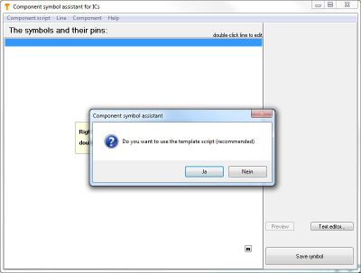
The most important information for our needs is the pin configuration, the packaging information as well as the block diagram. The Component symbol assistant asks us whether to use the recommended template script or not. Click "Yes" and the following dialog appears:
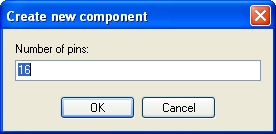
From the data sheet we know that the package has 20 leads so we enter this number. The appearing default script is the basis for the IC that we can see as a symbol on the right side.
Give it a name and define a target library
Changes of the script lead to changes of the symbol. For edition of an existing line double click it. Do so for the line COMPONENT. The following dialog appears:
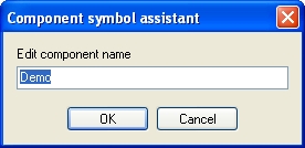
Change the name from "Demo" to "Microcontroller" and see the result in the script line. TARGET versions V14 and older have the line "LIBRARY" which defines the path to the library you wish the component to save in. From version V15 and younger the save decision is made later.
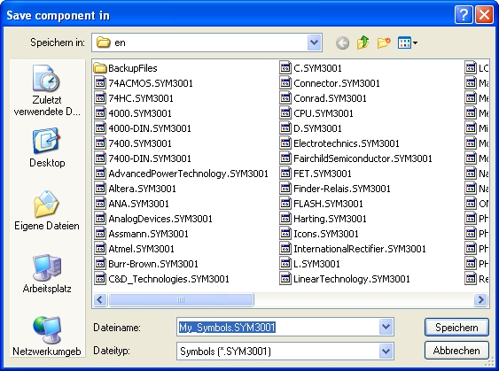
This image refers to versions V14 and older. Your image might look differently because your standard path might be different.
Assign a package proposal
This section also refers to versions V14 and older. V15 and younger does the assignment of a package later.
Back to the script: The line "PROPOSED_PACKAGE" assigns a package proposal to the symbol. The packaging information of the data sheet shows a package 20P3 DIP, an appropriate package proposal was DIL 20. Enter it with a double click M11 on the line and choose it from the flashing TARGET 3001! library browser.
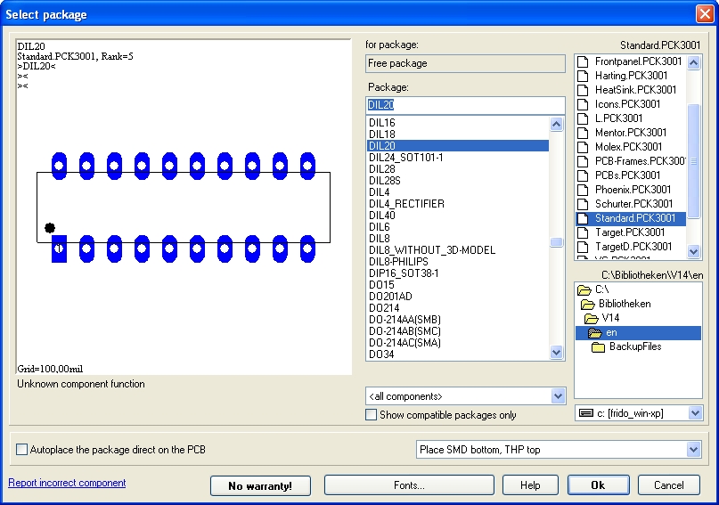
Again we learn how important it is to first create the package when creating a new component, because now you should be able to assign it as a proposal to the symbol. The same way we treat the next line for definition of the target library of the package proposal. As an example Standard.PCK3001 (this is the one the package DIL 20, which we already have, is in).
Now we proceed to line "COMPONENT_FUNCTION". For our component is a microcontroller with programmable flash, we enter "Flash" after double click upon the line. As "PREFIX" we enter "IC" and in line "TYPE": we enter "IC/Digital".
Now we are back in V15 and younger...
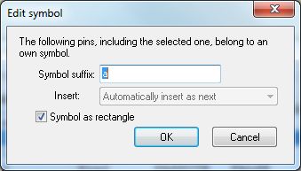
The dialog in line "SYMBOL" allows the definition of the suffix, here "a". You may know that the suffix is responsible for the order of placement if a component consists out of more than one gate. Gates a, b, c, d, will automatically be inserted after each other (=as next). Also the fact whether a symbol should receive a rectangular outline where the pins are assigned to can be selected here (theck the box...).
Assign Pin Functions
Now we have a look at the pin properties according to the data sheet. The following image shows the according section of the data sheet.
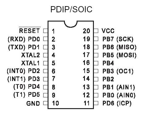
Let's start with pin number one, an inverted reset function. The block diagram of the data sheet shows that this connection is an INPUT.
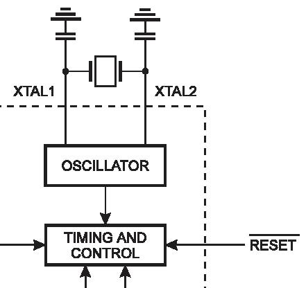
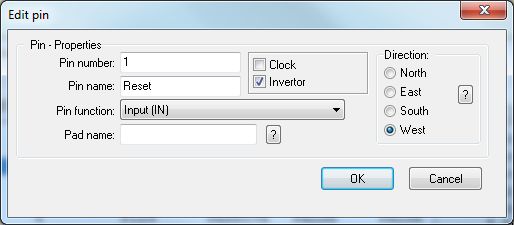
After doubleclick upon the first pin-line we enter "A1" as pad name for the corresponding pad of the proposed package. As pin number we enter "1" for it is the first pin. As pin name we enter "Reset" and as pin-function "Input(IN)". This entry may be chosen from the pull down list. Because it is an asynchronous reset (even if the clock is not running) we deactivate a "clock arrow" in the symbol view (in the script the word "FALSE" represents this entry). Activate the showing of an "inverter point" (in the script we see the word "TRUE"). Now we need to define the alignment, i. e. at which side of the symbol this pin should appear. Choose "WEST". After a click on OK the first pin is defined sufficiently.
With pin 2 we have one of the seven PortD drivers, see data sheet:

We double click upon the line of the second pin and enter the following settings:
Pin number: 2
Pin name: PD0
Pin function: In-/output (I/O) (see block diagram)
Pad name: A2
Clock arrow : not activated
Inverter point: not activated
Alignment: West
Press OK, second Pin done.
We double click upon the line of the thirdd pin and enter:
Pin number: 3
Pin name: PD1
Pin function: In-/output (I/O) (see block diagram)
Pad name: A3
Clock arrow : not activated
Inverter point: not activated
Alignment: West
Press OK, third pin done.
At that time we see in the Component Assistant the following picture:
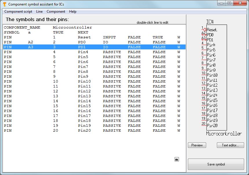
The image of the symbol on the right side is completed step by step with additional pin definitions.
Generate component
If all pins are defined and the desired settings are made, press button Generate component in menu Component. Now TARGET checks whether 20 pins (for a DIL 20 package) really do exist. If yes now the component symbol is generated to the database and you will be asked, which package you'd like to assign. If you got a little more familiar with the assistant, such a script can easily be generated more quickly with the help of a modern spreadsheets, maybe you can speed up the work (clicking 50 times or more the line "Pin" is not very comfortable. Just use the copy function in the spreadsheet. Do so also to the numbering functions...). You can also use a text editor as far as you follow the structure of the script and separate any entry with a tab. Import such a script.txt into the assistant as mentioned above.
Sort the order of the pins
New example:
In case you have a misorder of Pin Numbers somehow (regardless of the Pin Name)...
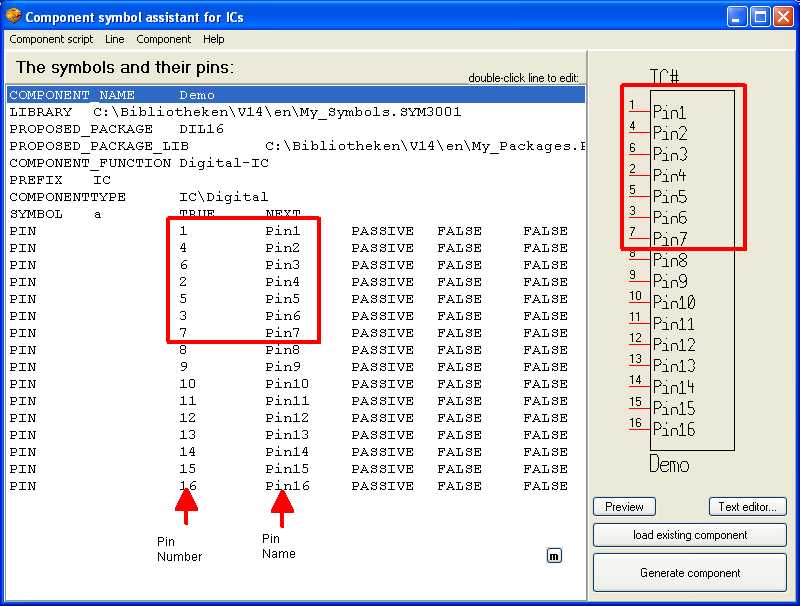
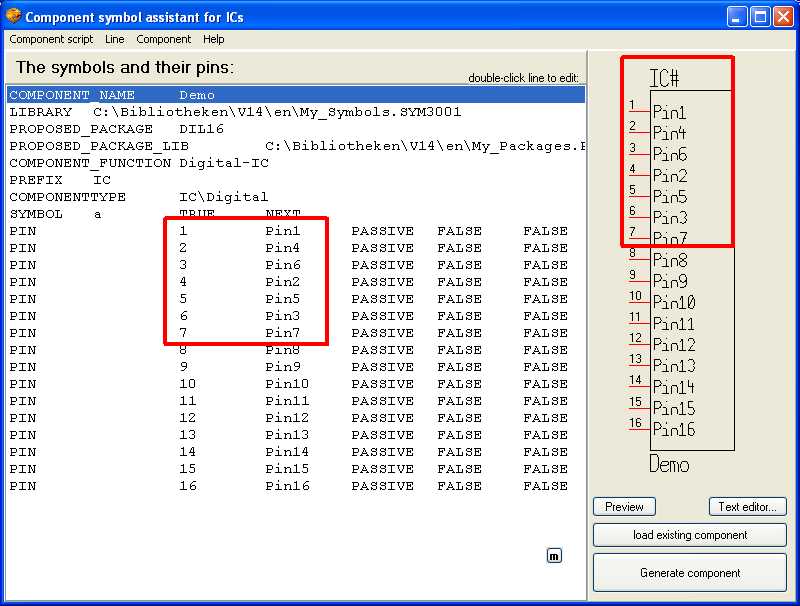
you can use the function

to bring them back in correct order (note the pin names to the right!)
Move pins to the other side
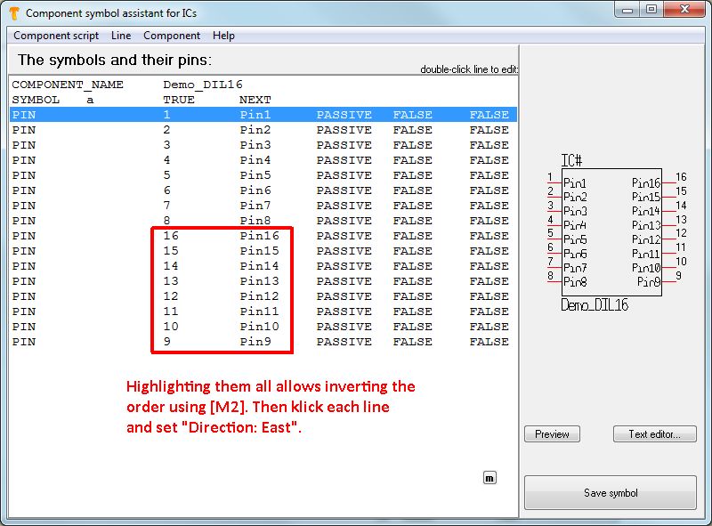
see this image:
 ]
]
Bringing a bunch of pins to the north or the south of the symbol will work the same.
See also Package assistant


