Package assistant
Preface
This assistant is made especially for packages with many pads on for instance all four sides e. g. SIL/SIP, DIL/DIP, SO, QFP, BGA etc. For other, smaller, package dimensions please see here: here.
Load existing package
If you want to edit an existing package or if you want to derive a new package from an existing one, please open the component browser with functional key [F2]. Search the component in question and click M2 on its package image in order to open a kontext menu. Now select option:Edit package with IC assistant....
The package assistant
Find the Package assistant in layout view Menu Package / "Package Wizard". After a click on it the dialog: "Package assistant for ICs" appears:
The contents of the dialog are identical to those of the symbol assistant but the arrangement of the Buttons give contribution to a more comfortable view of the drawings. Click on button script new and face a default script which we use for proceeding.
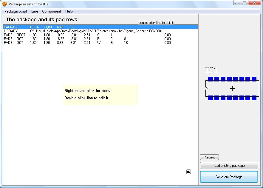
The first line of the script defines name, outer measurements and alignment of the package outline. A double click upon line 1 opens the following dialog:
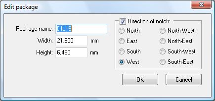
Width and Height of the package refer to the Data sheet, see "Packaging Information":
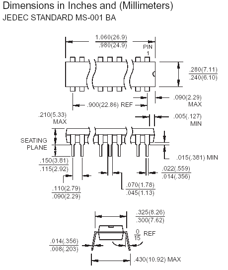
Enter a width of 26,9 mm and a height of 7,11mm. The notch of the component shows east.
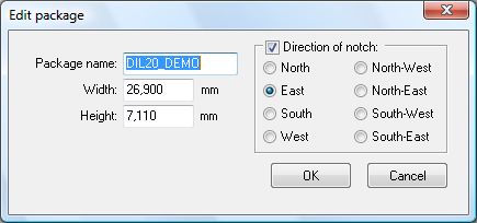
After confirmation with OK we see that the outline of the component shows the desired measurements. The following dialog defines the TARGET 3001! library the package shall be saved in.
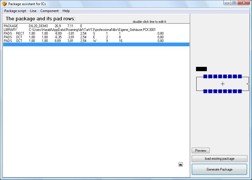
Doubleclick M11 on line "Library" opens the following dialog. Define the library to which the package shall be saved.
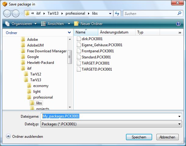
Now we proceed to the pad properties. A doubleclick upon the first line "Pads" leads to the following dialog:
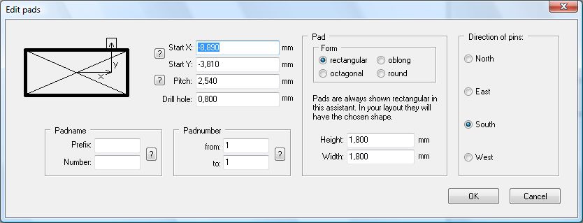
Let's start with Pad No 1 and its positioning.
The coordinate X represents the horizontal distance between center of package to center pin 1. The coordinate Y follows the same logic in vertical direction. The measurements of the pad itself are defined later.
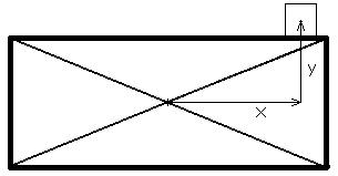
We calculate the value of X in mm by:

26,9mm is the overall width of the package and 2,79mm is the pitch (distance between two pins of the component). We take those values by the package information in the data sheet.
We calculate the value of Y in mm by:

Rounded to Y = 4,13 seems sufficient.
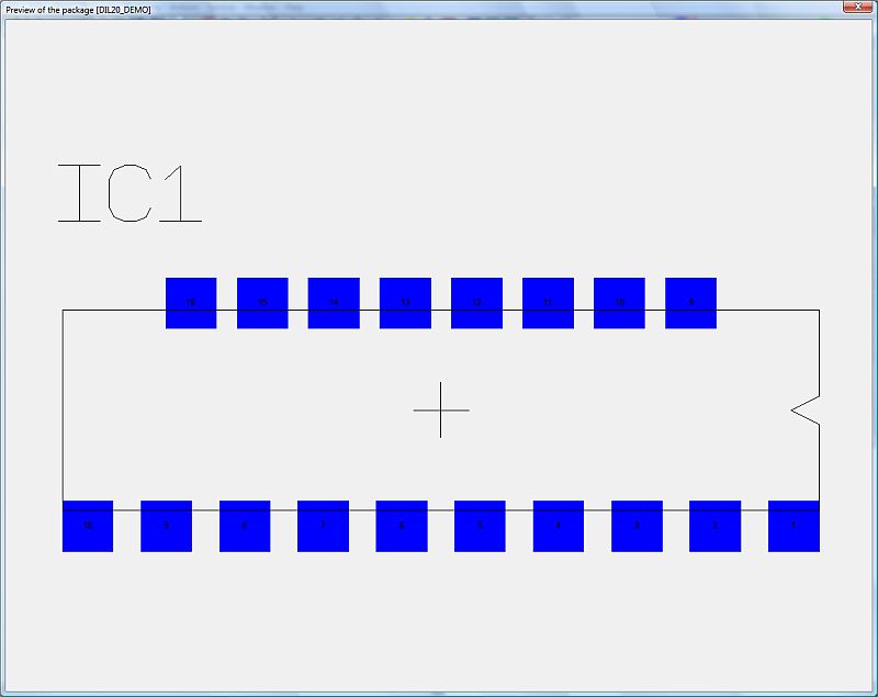
In the above formula 7,11mm is the height of the package. The value 8,26mm includes additionally the width which the pins reach out of the package outline on both sides. Those data we find in the package information also. Set the pitch to 2,79mm and the width for the drill hole to 0,8mm. The pad number starts with 1 and ends in the row north of the package with 10. As pad form choose octagonal (to be seen in the layout later), pad height and width set 1,8mm each. As direction please set "west" which means pad 1 is the east one, pad 2 besides it to the west and so on.
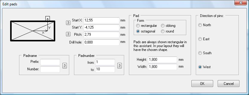
Now the first row of the pads is positioned. Pad names (Prefix and Number) are requested only when designing a BGA. Their logic then follow the same as the definitions on the squares on a chess-board. The First line is named A, the second B and so on. The first column is 1, the second 2 and so on. The following picture shows the pad view when A1 to A10 is set. The upper dialog by the way does not have those entries.
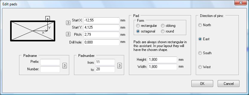
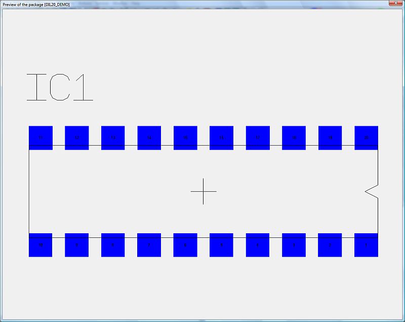
Now we design the lower row of pads. The position of pad 11 is the same as pad 1 but with negative sign. So we enter the data to the dialog and take care that the direction of numbers and positions show east.
After confirmation with OK we see the following picture:
As far as all pad settings are correct, we generate the package. The following dialog appears:
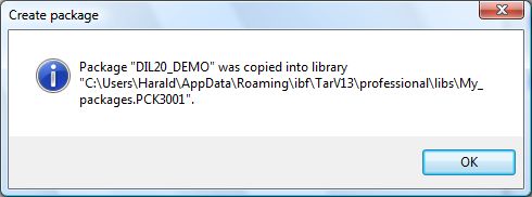
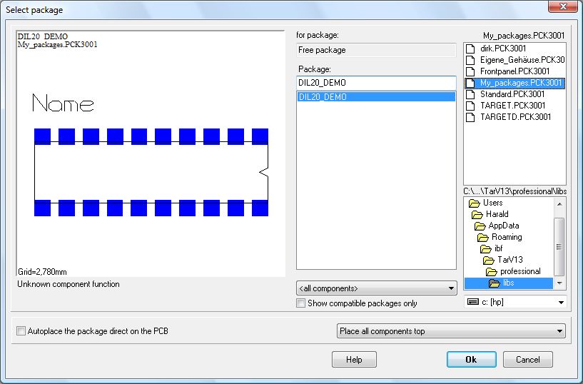
For a check please open the library browser and import the new package to an empty layout page.
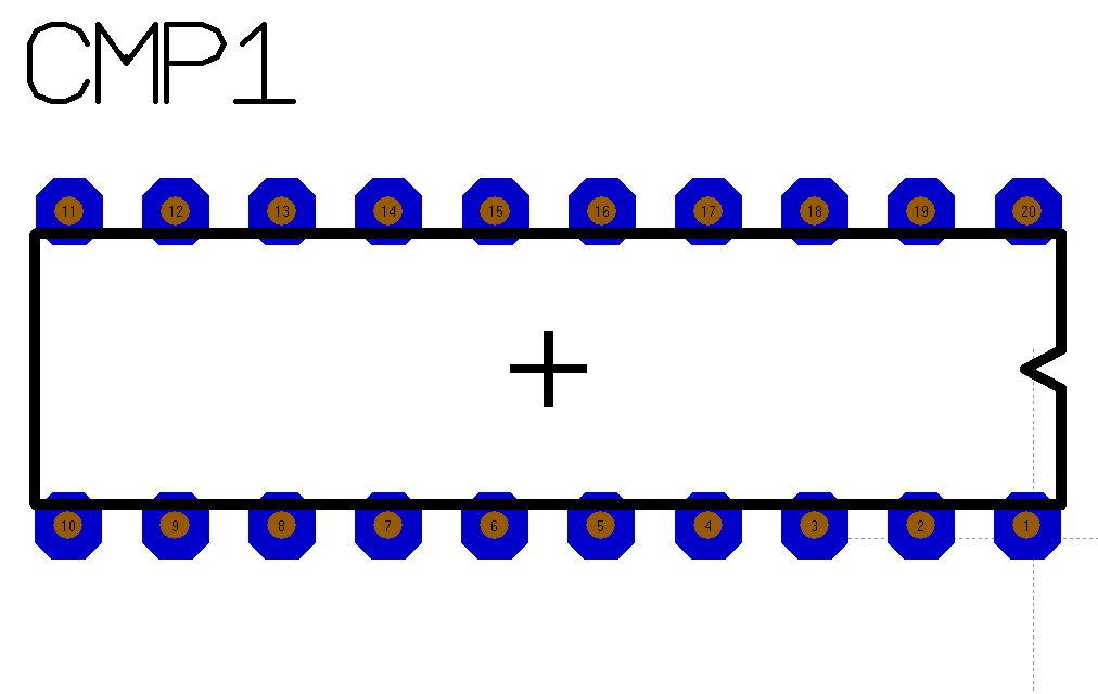
We see: the pads appear octagonal.
We can edit and import the script the same as the symbol assistant with a spreadsheet or a simple text editor.
See also Symbol assistant

