Créer un nouveau composant : Différence entre versions
(→Le premier dialogue) |
|||
| Ligne 6 : | Ligne 6 : | ||
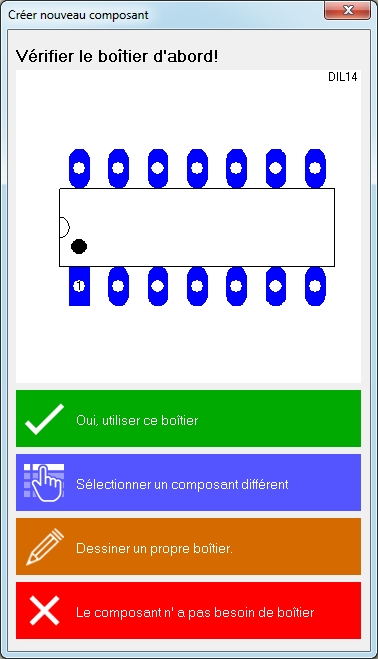
<br>[[Image:NeuesBtlErstellenDlg_f.jpg|378px|left|Le dialogue Créer nouveau composant|Image 1: Le dialogue Créer nouveau composant]] Tout d'abord décidez quel boîtier (le dessin de surface portante et le contour de boîtier) vous souhaitez utiliser.<br><br> | <br>[[Image:NeuesBtlErstellenDlg_f.jpg|378px|left|Le dialogue Créer nouveau composant|Image 1: Le dialogue Créer nouveau composant]] Tout d'abord décidez quel boîtier (le dessin de surface portante et le contour de boîtier) vous souhaitez utiliser.<br><br> | ||
| − | Si vous devez de '''"Dessiner un propre boîtier"''' parce que vous ne trouvez pas un approprié entre les existants, demarrez le processus de | + | Si vous devez de '''"Dessiner un propre boîtier"''' parce que vous ne trouvez pas un approprié entre les existants, demarrez le processus de création utilisant le baguette magique dans le barre laterale à gauche. Ici utilisez les assistants suivants:<br> |
| − | * [[ | + | * [[Générateur de boîtier]] |
| − | * | + | * Dériver le boîtier d'un boîtier existant (vous devez connaître le nom du boîtier!) |
| − | * [[ | + | * [[Assistant pour les boîtiers|Création d'un boîtier ]]<br><br> |
| − | + | Seulement si vous ne pouvez utiliser un assistant pas vous devriez dessiner un contour de boîtier et placer les pastilles à la main. Comment faire au mieux lisez ici s.v.p: | |
| − | '''[[ | + | '''[[Créer un composant]]'''<br> |
Save the package afterwards to the data base using a suitable name and open menu item "Create a new component" '''again'''. Now click the blue panel "Select a different package" and select the one you just have drawn.<br> | Save the package afterwards to the data base using a suitable name and open menu item "Create a new component" '''again'''. Now click the blue panel "Select a different package" and select the one you just have drawn.<br> | ||
Continue top left with the magic wand in order to create a symbol: | Continue top left with the magic wand in order to create a symbol: | ||
Version du 18 mai 2016 à 12:01
Trouvez cet option dans menu de schema: Composants/Créer un nouveau composant...
Cette zone vous guide étape par étape pour créer un nouveau composant. Des composants déjà existants, similaires ou ses éléments peuvent être utilisés. Toutes les fonctions automatiques sont proposées au cours de ce processus afin que vous le plus rapidement serez en mesure d'utiliser votre composant désiré sans double emploi inutile.
Sommaire
Le premier dialogue
Tout d'abord décidez quel boîtier (le dessin de surface portante et le contour de boîtier) vous souhaitez utiliser.
Si vous devez de "Dessiner un propre boîtier" parce que vous ne trouvez pas un approprié entre les existants, demarrez le processus de création utilisant le baguette magique dans le barre laterale à gauche. Ici utilisez les assistants suivants:
* Générateur de boîtier
* Dériver le boîtier d'un boîtier existant (vous devez connaître le nom du boîtier!)
* Création d'un boîtier
Seulement si vous ne pouvez utiliser un assistant pas vous devriez dessiner un contour de boîtier et placer les pastilles à la main. Comment faire au mieux lisez ici s.v.p:
Créer un composant
Save the package afterwards to the data base using a suitable name and open menu item "Create a new component" again. Now click the blue panel "Select a different package" and select the one you just have drawn.
Continue top left with the magic wand in order to create a symbol:
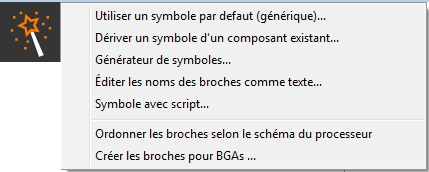
Image 2: The options of the magic wand when creating a schematic symbol.
Use a standard symbol (generic)
Maybe a 'standard symbol (a generic) matches. Select one from the list.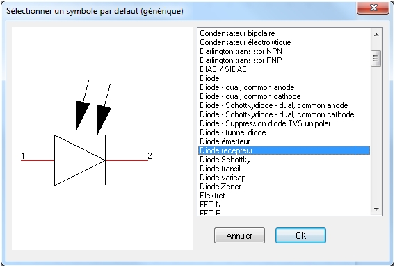
Image 3: Select a generic symbol.
Generic is just another word for "default" or "primitive". Maybe you need to check the pin numbering of the generic symbol and synchronize it with the pad numbering of the package. For this reason a separate dialog will open. Pin number and pad number (cipher) need to be identical. It's just the same cipher of pin and pad which cares for their logical/electrical linkage.
Derive symbol from existing component
Eventually you can derive a new symbol from an existing component. The idea is to copy a symbol of an existing component to your canvas in order to modify it independently from its source.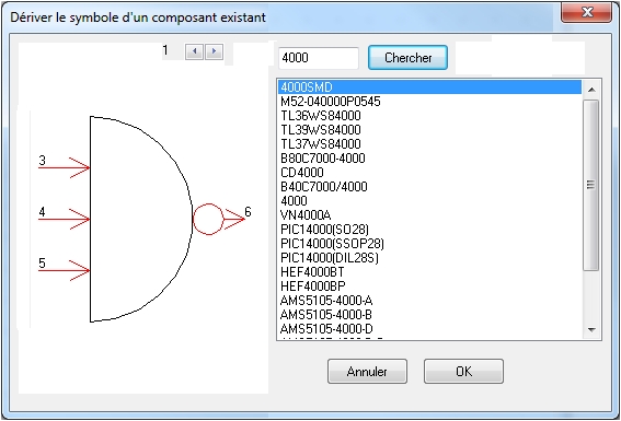
Image 4: Derive a symbol from an already existing component. Enter the component name to the search line. Now the symbol appears on the canvas and you can modify it as you please.
Symbol generator
Create an individual symbol by the use of the Symbol-Generator:
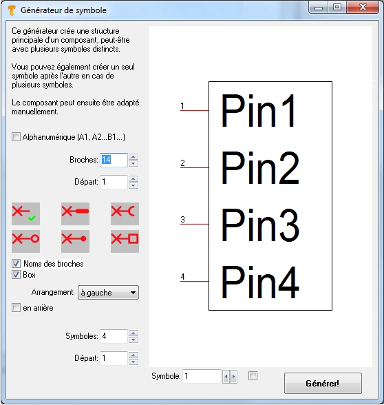
Image 5: The symbol generator creates a basic structure of a symbol.
In this case it has 14 pins made of four sub symbols (three by four pins plus two). The first sub symbol is shown here, the last one will be treated as a "rest" (see ticked box at "last symbol as rest". The tick at "Alphanumeric" places characters and ciphers instead of subsequent numbers. Like a matrix: A1, A2, ... B1, B2, ...
The field: "Arrangement" defines the suggestion for a positioning of the overall number of pins at the new symbol. In our case the pins shall be placed left.
Result of the settings according to the above dialog:

Image 6: A 14 pin symbol with 4 sub symbols, see indices at the component handles. The last one is treated as "Rest".
Edit selected pin names in a text editor
there is a link to another source: Edit selected pin names in a text editor:
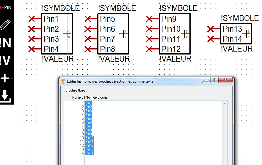
Image 7: Highlight pins in the symbol, all or only parts of them. Take the pin names (from the data sheet or from any other digital source) to your clipboard and paste them to the text area of the dialog. They come in maybe a bit weird but - no worry - you can arrange the text corretly so that every pin number has the right pin name aside. That's all. For Ball Grid Arrays (BGA), having a matrix structure, pin-numbers can be displayed alphanumeric. This eases the assignment of pin names coming from the clipboard.
Symbol via script
This assistant allows the creation of a symbol using a script.
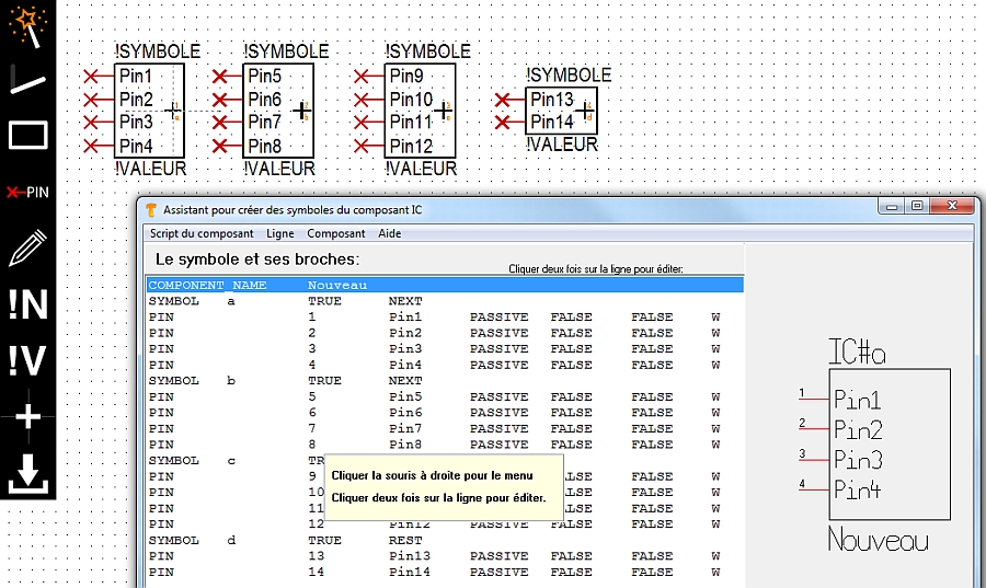
Image 8: The symbol assistant: Double click a line to edit a pins properties.
Order Pins according to processor scheme
There is a separate article on this topic. Please follow the link: Arrange pins according to processor scheme
Create a symbol like a ball grid array (BGA)
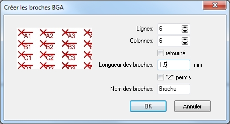
Image 9: The dialog "Create BGA pins"
The checkbox "flipped" means that the naming of rows and columns get mirrored by its diagonal: Line A gets row A and vice versa. The checkbox "Z" allowed means: Character Z can easily be mixed up with cipher 2 which can lead to uncertainties in naming the matrix nodes. Nevertheless you can use a Z: Tick the box.
fr:Créer un nouveau composant


