The Dialog for STEP 3D Export
Abstract
STEP = STandard for the Exchange of Product model data
Find the dialog for the STEP Export in menu:
File|Input/Output Formats|File transfer/documentation|Step export(3D)...
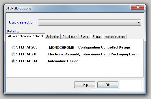
Image 1: The Step Export Dialog as it opens. It consists of the main sections Quick selection and Details.
The section Quick selection

Check the complete PCB with an external CAD for the housing
Use this option if you want to give over the complete assembly (PCB including all devices assembled). Only the inner details of the PCB body which can't be seen from outside are omitted. The ground plane is idle here but can be added later.
Check the pure PCB only with an external CAD for the housing
Use this option if you want to give over only the PCB body. This means only the part which is manufactured in FR4 material.
Simulate the electrical functions of the PCB with external tools
Use this option in order to give over the PCB body with all inner and outer technical details (tracks, pads, vias, drill holes...) without components.
The section Details
Select from the following tabs:
AP = Application Protocol
An AP covers a particular application and industry domain:
- AP 203 Configuration Controlled Design
- AP 210 Electronic Printed Circuit Assembly, Design and Manufacturing
- AP 214 Core Data for Automotive Mechanical Design Processes
Only some APs are implemented in your 3D program. AP 203 is a basic AP which at least will be supported by your system. You will notice only one difference in the data:
- STEP AP 203: singlecolor
- STEP AP 210: multicolor
- STEP AP 214: multicolor
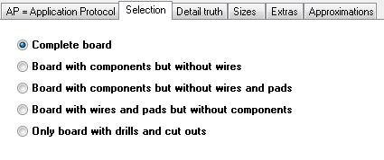
Selection
In tab Selection determines which elements are going to be overgiven to the STEP format. No changes have taken place here since the last version.
Detail truth
Detail truth means model fidelity - the model's level of matching with reality.
Components in color or monochrome.
Output PCB outline with exact coordinates:
The normal algorithm to calculate the PCB outline shows an inaccuracy of some µm. The outline of the PCB optionally can be calculated by a more accurate algorithm.
The outline of the PCB is calculated by an algorithm which shows an impreciseness of a few µm. You can select a precise algorithm which avoids this.
Output ground plane:
A ground plane can be converted to STEP though in the TARGET 3D viewer upt to now (may 2014) it can not be displayed. Activate this box if indicated.
Output details for simulators (conducting via hull and solder with THT):
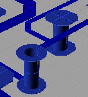
Abundance of details goes along between the poles of necessity and file size. To simulate the electrical behaviour of the 3D PCB sufficiently details are needed. Tick the box here so that the STEP exportembraces it accordingly. Ground planes and assemblies are ticked automatically. The quick selection also ticks the required boxes automatically. "Components" are unticked because they aren't needed for simulation.
The layout of the printed circuit board, the placement of the components and the structure of the power layer can have its own effect on the electrical performance of the circuit. There may be problems with EMC, power integrity and signal integrity. Below you will find helpful links on the subject. By this means you can analyse your board on such effects for example using the simulation tool CST.
https://www.cst.com/Products/CSTPCBS
https://www.cst.com/Applications/Category/Signal+Integrity+and+Power+Integrity
https://www.cst.com/Applications/Article/Signal-Integrity-Analysis-Of-A-Complex-Multi-Layered-Package
http://en.wikipedia.org/wiki/Signal_integrity
http://en.wikipedia.org/wiki/Computational_electromagnetics
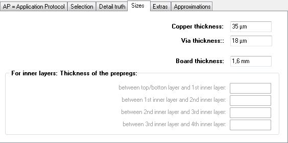
Sizes (= parameters)
Extras
Also see chapter 5 at option "Locking all parts of an imported STEP assembly e.g. in Solidworks".
Using the option "Generate assemblies..." the STEP-Import in your CAD might show a hint e.g. in Rhinoceros
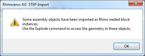
In your CAD there will be a function "Explode", which is able to divide objects in a hierarchy (cascading).
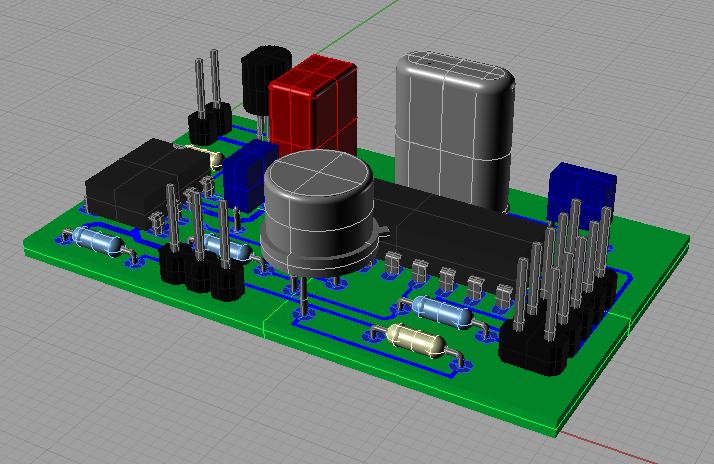
PIC exploded:
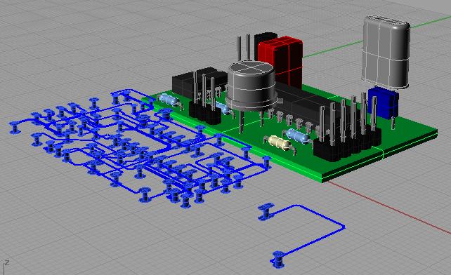
Important element groups can be divided into various sub entities. A first explosion separates the following objects:
- PCB body
- electroconductive objects (Tracks, Pads, Vias, Ground planes...)
- component 1
- component 2
- component ...
In this first stage of explosion within your 3D CAD system it is possible to assign material properties (e.g. "copper") to the electroconductive objects of your projects. Now let the electroconductive parts explode again so that single signals for instance can be touched/inspected/treated separately (galvanic separation).
Approximations
Some 3D programs offer only a rudimentary STEP import. Some STEP surfaces e.g. CYLINDRICAL_SURFACE are not implemented or inaccurate. These surfaces can be approximated by a polyhedron; i.e. made up of only PLANEs.
File load time
It takes some minutes to load a STEP file! This load time increases if some polyeder approximations are applied. A 3D viewer does the import much faster than a 3D-CAD program! Currently implemented STEP elements: CARTESIAN_POINT, VERTEX_POINT, LINE, CIRCLE, PLANE, CYLINDRICAL_SURFACE, TOROIDAL_SURFACE, SPHERICAL_SURFACE, DIRECTION, VECTOR, AXIS2_PLACEMENT_3D, ADVANCED_FACE, FACE_BOUND, FACE_OUTER_BOUND, ORIENTED_EDGE, EDGE_CURVE, EDGE_LOOP, CLOSED_SHELL, MANIFOLD_SOLID_BREP, STYLED_ITEM, MECHANICAL_DESIGN_GEOMETRIC_PRESENTATION_REPRESENTATION
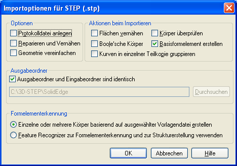
Switch off all options to reduce load time in Solid Edge:
Locking all parts of an imported STEP assembly e.g. in Solidworks
Selecting the option "Ausgabe für Solidworks optimieren" in tab "Extras" and not selecting the option "Baugruppen erzeugen" does not deliver any assemblies. So you'll get fixed/locked elements. As soon as you generate assemblies the following problem occurs:
STEP does not offer any options to fix/lock (sub-)assemblies. If you for example export the Solidworks sample "box_with_lid" as STEP and import it again, assemblies are not fixed any more.
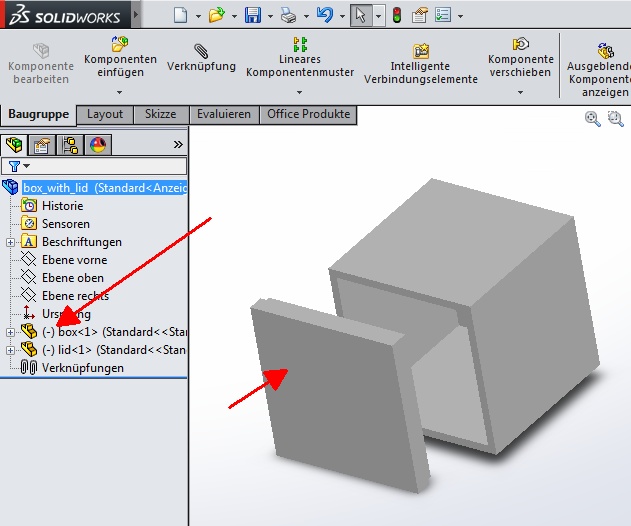
Image: Fixations are not available in STEP.
Link to this thread into the Solidworks-Forum:
https://forum.solidworks.com/thread/49885
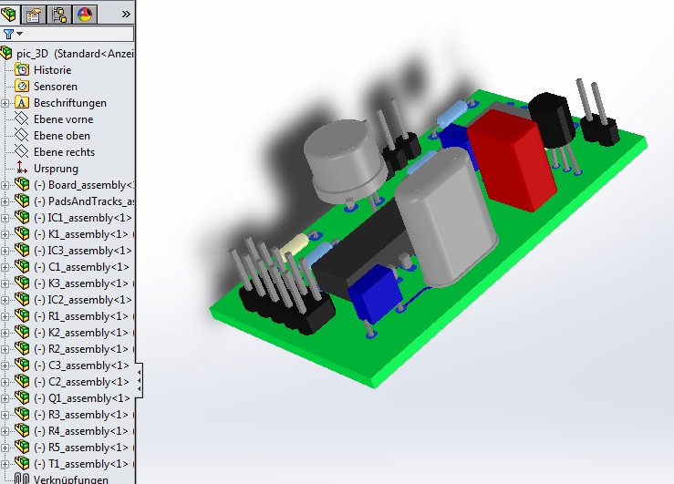
Image: If you export the TARGET project pic.T3001 to STEP and import it to Solidworks, the subassemblies are not fixed any more.
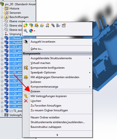
Image: Highlight all subassemblies and select option "Fix".
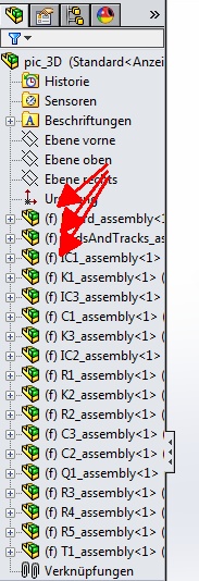
Image: Subassemblies are fixed now and provided with the prefix (f).
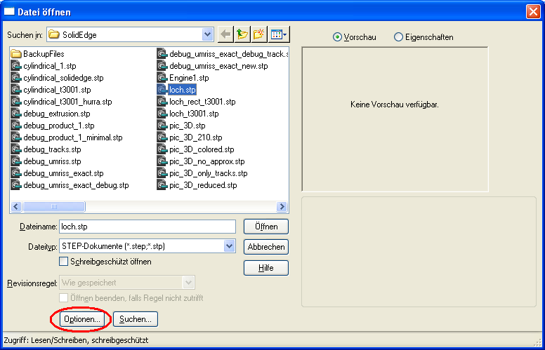
In the solidworks "file open" dialog STEP can be chosen. In this dialog there is a button "Options". Here you can manipulate the STEP-Import as you please.


