Difference between revisions of "Signal polygon"
(→General) |
|||
| Line 14: | Line 14: | ||
*by item "6 Draw ground polygon" in menu "Elements" or | *by item "6 Draw ground polygon" in menu "Elements" or | ||
*by icon [[Image:PolySignal.jpg]] among the drawing functions [[Image:Pen.jpg]]<br><br><br> | *by icon [[Image:PolySignal.jpg]] among the drawing functions [[Image:Pen.jpg]]<br><br><br> | ||
| + | |||
| + | |||
== What you can do == | == What you can do == | ||
| Line 22: | Line 24: | ||
| − | <b>Layer:</b> | + | <b>Layer:</b> a polygon with signal assignment can only be created on a copper layer. The copper layers used in your project can be selected from the drop down list. Select the copper layer upon which your polygon later shall appear (copper bottom, copper top, copper inside). <br><br> |
| − | <b>Signal:</b> | + | <b>Signal:</b> Select the signal to be assigned to the polygon. At this point you can only assign one signal to one polygon. Creating a [[Star shaped ground]] is a separate topic. Please have a look there.<br><br> |
| − | <b> | + | <b>Track width:</b> In easy words track width is the thickness of the pen which you use to fill the polygon with color. Sounds a bit childish but in respect to the production technique it is the best way to compare. In Gerber a photo pen follows the lines on a photosensitive board with an aperture according to the track width. The sharper the tip of the pen, the more filigree structures can be built. Discuss the smallest value with your PCB-house. Here in Europe the minimum value of 0.15 mm is common.<br><br> |
| − | + | The following picture shows the polygon with a little notch see arrow. The reason is a track width set too wide. The pen can not go through this bottle neck.<br><br> | |
| − | [[image:signalpolygone_gap.jpg| | + | [[image:signalpolygone_gap.jpg|Track width too big]]<br>Track width too big to close the area at this spot.<br><br> |
| − | + | Referring to the track width set here the DesignRuleCheck later checks whether the minimum track width od a connection is fulfilled. The track width must also be seen in combination with the "Grid spacing". A gridded ground plane in consists of a net-structure made of orthogonal intersecting lines. The width of this lines you also define here. You can only enter one value for the track width here. The net structure (= ground plane in lines) always has a square mesh structure.<br><br> | |
| − | <b> | + | <b>Grid spacing:</b> A ground plane in lines offers production advantages in galvanization and also is preferable in respect to electromegnetic performance of the signal. In addition to the track width you can define the distance of the mesh.<br><br> |
| − | [[image:signalpolygone_grid.jpg| | + | [[image:signalpolygone_grid.jpg|Ground plane in lines]]<br>Copper top: Ground plane in lines (to the right). Track width: 0.3mm, Grid spacing: 0.5mm<br><br> |
Revision as of 15:55, 26 July 2017
![]()
Icon to be found in the layout view among the drawing functions
General
A signal polygon can be handled like a separate ground plane. It can individually be furnished with attributes. On one copper layer any number of polygones with different signals can be drawn.
You can reach this mode:
- by keyboard key [6],
- by item "6 Draw ground polygon" in menu "Elements" or
- by icon
 among the drawing functions
What you can do
Define the corners of the polygone by M1. You can close the polygone automatically by [Return] when drawing the last segment. M2 does the same so that you end the line exactly on the starting point. Immediately the dialog for edition of the signal polygon opens.
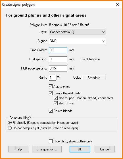
The dialog for signal polygon edition
Layer: a polygon with signal assignment can only be created on a copper layer. The copper layers used in your project can be selected from the drop down list. Select the copper layer upon which your polygon later shall appear (copper bottom, copper top, copper inside).
Signal: Select the signal to be assigned to the polygon. At this point you can only assign one signal to one polygon. Creating a Star shaped ground is a separate topic. Please have a look there.
Track width: In easy words track width is the thickness of the pen which you use to fill the polygon with color. Sounds a bit childish but in respect to the production technique it is the best way to compare. In Gerber a photo pen follows the lines on a photosensitive board with an aperture according to the track width. The sharper the tip of the pen, the more filigree structures can be built. Discuss the smallest value with your PCB-house. Here in Europe the minimum value of 0.15 mm is common.
The following picture shows the polygon with a little notch see arrow. The reason is a track width set too wide. The pen can not go through this bottle neck.
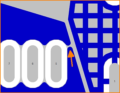
Track width too big to close the area at this spot.
Referring to the track width set here the DesignRuleCheck later checks whether the minimum track width od a connection is fulfilled. The track width must also be seen in combination with the "Grid spacing". A gridded ground plane in consists of a net-structure made of orthogonal intersecting lines. The width of this lines you also define here. You can only enter one value for the track width here. The net structure (= ground plane in lines) always has a square mesh structure.
Grid spacing: A ground plane in lines offers production advantages in galvanization and also is preferable in respect to electromegnetic performance of the signal. In addition to the track width you can define the distance of the mesh.
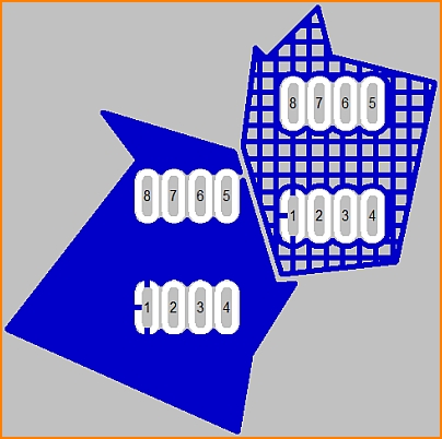
Copper top: Ground plane in lines (to the right). Track width: 0.3mm, Grid spacing: 0.5mm
Rand-Abstand: Ein Abstand einer Potenzialfläche zum Rand der Platine kann einen Kurzschluss durch bloßen Kontakt oder Signalübersprung beim Einbau der Platine verhindern. Bestimmen Sie hier, wieviel mm Ihre Potenzialfläche vom Rand der Platine (= Mitte Strich des Platinenumrisses) zurückgesetzt sein soll.
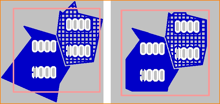
Abstand vom Platinenrand: links ohne, rechts mit Zurücksetzung vom Platinenrand. Im Bild rechts hat das linke Polygon einen Rand-Abstand von 0,8mm, das rechte Polygon hat einen Rand-Abstand von 0,4mm.
Rang: Mehrere Potenzialflächen können sich überlappen, können sogar ineinander verschachtelt sein, dürfen sich dabei aber nicht berühren. Welche Fläche die dominante ist, die also der anderen Fläche etwas weg nimmt, bestimmt sich durch ihren Rang. Je höher die Rangziffer einer Fläche ist, umso dominanter ist sie. Eine Fläche mit Rang 2 dominiert eine Fläche mit Rang 1, nimmt ihr bei Überschneidung also den Bereich der Überschneidung weg. 99 Ränge sind möglich.
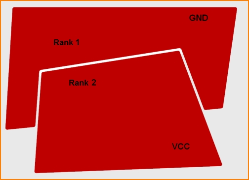
Kupfer unten: Verschachteln von Polygonen mit unterschiedlichen Signalen und unterschiedlichem Rang
Wärmefallen erzeugen: Der Lötpunkt eines Bauteilbeinchen mit dem gleichen Signal wie die Fläche, z. B. GND müsste vollflächig eingebettet sein um bestmöglich angeschlossen zu sein. Beim Löten allerdings würde zu schnell zu viel Wärme in die Massefläche abfließen, so dass sich das Lot nicht optimal mit dem Kupfer verbindet. Als Wärmefalle bezeichnet man einen Lötpunkt, der stattdessen mit einem Sicherheitsabstand (Aura) umgeben ist und lediglich mit kleinen Stegen an die Massefläche angeschlossen ist. Dadurch fließt die Wärmeenergie beim Löten nicht zu schnell in die Fläche ab. Diese Stege können kreuzförmig, y-förmig oder gradlinig sein. Siehe auch Thermal Pads .
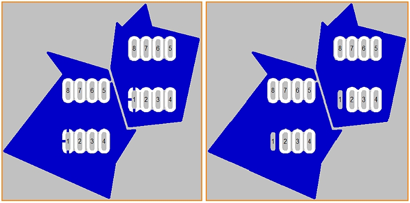
Die Pads Nummer 1 von zwei Bauteilen in zwei Potenzialflächen. Links mit Wärmefallen, rechts ohne.
Inseln entfernen: Ein nicht angeschlossenes Stück einer Potenzialfläche heißt "Insel". Man kennt auch den Begriff "schwebende Massefläche". Sie haben keinen Zweck und stören nur. Deshalb entfernt man sie. TARGET macht das automatisch, wenn Sie den Haken hier setzen. Der Anschluss einer Massefläche erfolgt durch ein angeschlossenes Pad eines Bauteils, einer Durchkontaktierung mit Aura 0 auf dieser Ebene oder ein Stück Leiterbahn durch die Fläche mit Aura 0. Immer muss der Signalname (=das Signal) identisch sein.
Sofort füllen: Das Polygon wird sofort im Zusammenspiel mit anderen Polygonen und Elementen unter allen Aspekten erzeugt. Dieser Prozess kann in größeren Designs unter Umständen einige Sekunden dauern. Deshalb kann man dies hier kurzfristig abschalten.


