Several freehand groundplanes
Also see Article Groundplane
Maybe you desire to shield several feed-in signals upon one copper layer each with a groundplane. Such a construction in TARGET 3001! is easy and requires only few steps. The logic is the same as with a single Freehand groundplane - simply duplicated.
Precondition is, that all signals need to be routed prior to creating groundplanes.
- Create a Freehand groundplane segment having a certain signal (eg. GND) upon one copper side
- Create a second Freehand groundplane segment carrying a different potential (eg. VDD) upon the same copper side
The next step is embedding the desired signal track segments into "its" groundplane. This is managed by setting the aura to zero. All other tracks leading a signal different to the signal of the groundplane in question keep their aura because they might run through a groundplane with a different signal.
EXAMPLE:
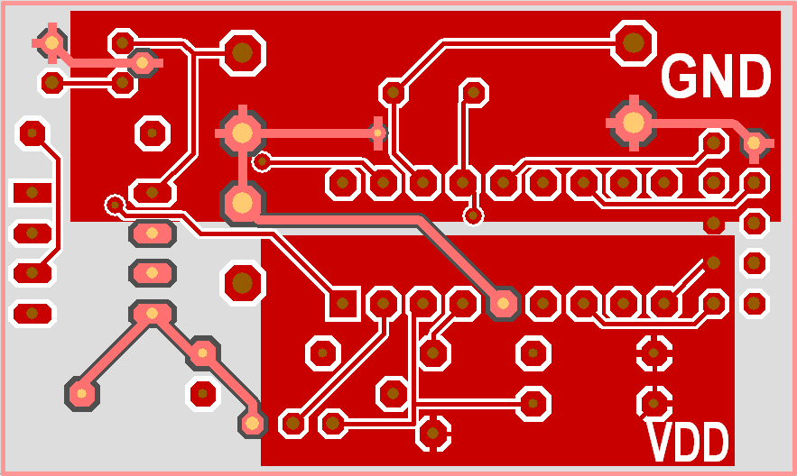
In the following layout 2 groundplanes shall be created, both upon layer 2=copper bottom (red). One groundplane shall carry signal GND the other one VDD. We start with the drawing of a solid rectangle for the GND-groundplane upon layer 0=Area bottom. This rectangle achieves signal GND (M11 on the rectangle opens the "Change rectangles" dialog for assigning a signal from a drop down list).
Image 1: Signal GND highlighted. That's how it runs on copper bottom. Within the GND groundplane its aura = 0.
Now set the aura of all GND-segments running through the GND groundplane = 0. Use this pointer setting: ![]() for highlighting one signal segment from pad to pad. Later view in light red those GND segments which run through the GND groundplane. To highlight the complete GND signal without the groundplane GND, please use this pointer tool:
for highlighting one signal segment from pad to pad. Later view in light red those GND segments which run through the GND groundplane. To highlight the complete GND signal without the groundplane GND, please use this pointer tool: ![]() .
.
Do the same with the VDD signal. Draw a rectangle (or any other solid/filled shape) upon layer 0, assign signal VDD to it and delete the aura at all parts of the VDD signal which lead through the VDD plane. The following image shows the complete signal VDD highlighted. You see the lighter red segments of the VDD signal having an aura and not:
Image 2: Signal VDD highlighted. That's how it runs on copper bottom. Within the VDD groundplane it's aura =0.
Besides: The lettering GND and VDD are written upon layer 1=Deletion bottom using the Text function. For reasons of readability on screen they have not been mirrored. If you want to see the lettering in reality upon the bottom side of your physical PCB, you need to mirror them.
Alias: partition, partitioning


