Difference between revisions of "Reference Symbol"
| Line 1: | Line 1: | ||
| − | A reference symbol | + | == General == |
| + | |||
| + | A reference symbol is used in the schematic. Visually not connected islands of the same signal or connections over several schematic pages must show their correspondence/equivalent by the help of reference symbols. Often power supply connections are drawn by arrows and ground symbols. A reference symbol for example looks like one of these:<br><br> | ||
[[Image:e_reference.jpg|none]]<br><br> | [[Image:e_reference.jpg|none]]<br><br> | ||
| + | |||
| + | |||
| + | == Insert a Reference symbol == | ||
| + | |||
Click [[Image:Ref.jpg]] under [[Image:InsertComponent.jpg]]<br><br> | Click [[Image:Ref.jpg]] under [[Image:InsertComponent.jpg]]<br><br> | ||
| Line 9: | Line 15: | ||
| − | + | To start such a connection use this menu command, click on the button shown above or simply press the '''[R]''' key in the schematic view. The dialog opens to select the preferred reference symbol. Later, after connection, the visible pin name must match with the signal name.<br><br> | |
| − | |||
| − | The dialog opens to select the preferred reference symbol. Later, after connection, the visible pin name must match with the signal name. | ||
| Line 21: | Line 25: | ||
[[Image:RefsInUse.jpg|none]]Reference symbols used in a schematic with several pages. Refs can have various looks and various meanings. At the end they all carry a signal.<br><br><br> | [[Image:RefsInUse.jpg|none]]Reference symbols used in a schematic with several pages. Refs can have various looks and various meanings. At the end they all carry a signal.<br><br><br> | ||
| + | |||
| + | |||
| + | == Editing Reference symbols with pages == | ||
| + | |||
| + | A reference symbol can show on which pages else the signal occurs. Please have a look here:<br> | ||
| + | [[Editing Reference symbols with pages]]<br><br> | ||
| + | |||
== Design your own kind of reference symbol == | == Design your own kind of reference symbol == | ||
Revision as of 11:06, 21 March 2019
Contents
General
A reference symbol is used in the schematic. Visually not connected islands of the same signal or connections over several schematic pages must show their correspondence/equivalent by the help of reference symbols. Often power supply connections are drawn by arrows and ground symbols. A reference symbol for example looks like one of these:
Insert a Reference symbol
Click ![]() under
under ![]()
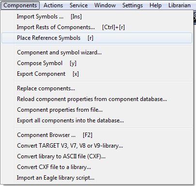
or press keyboard key [R] or use item "Place Referencs Symbols" in menu "Components".
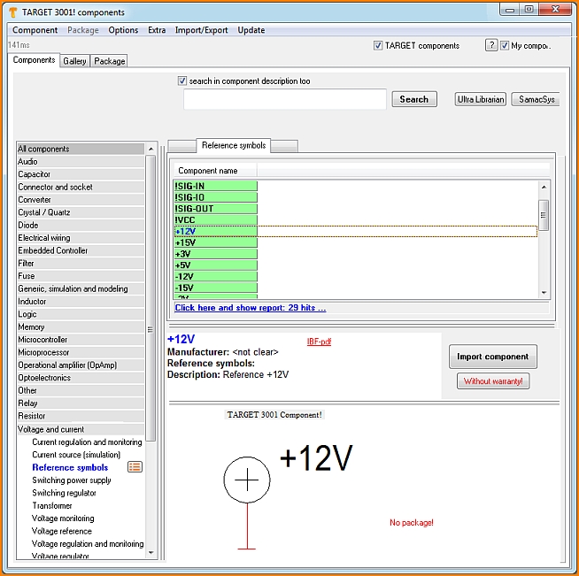
To start such a connection use this menu command, click on the button shown above or simply press the [R] key in the schematic view. The dialog opens to select the preferred reference symbol. Later, after connection, the visible pin name must match with the signal name.
If not, please edit the reference symbol after its placement with M11 (Change pin name). You can use reference symbols to create connections over several schematic pages. See also Edit component.
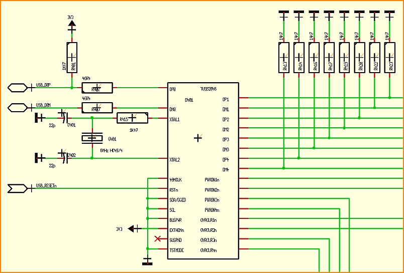
See Reference symbols in use in this example:
Editing Reference symbols with pages
A reference symbol can show on which pages else the signal occurs. Please have a look here:
Editing Reference symbols with pages
Design your own kind of reference symbol
Signals in the schematic which need to be carried over several schematic pages or ilands of the same signal not being linked optically can be assigned to each other by the use of Reference symbols.
When creating a Reference symbol the following aspects need to be regarded:
Open a new project showing an empty schematic page. Automatically it will be named: NewProject.jpg.
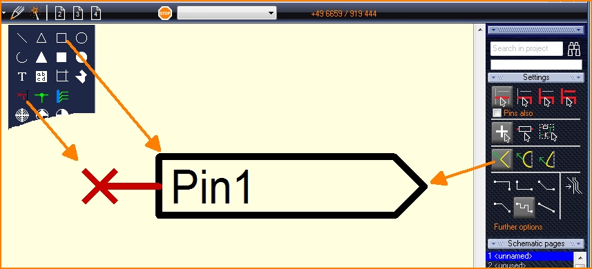
Draw the reference symbol using the drawing functions of TARGET 3001! (line, connection pin, etc.).
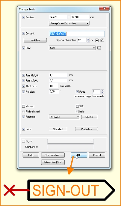
Click M11 upon the pin name, the dialog "Change Texts" will open.
Enter the desired pin name in the "Content" field, e. g. SIGN-OUT.
Highlight the reference symbol (drawings, connection pin) completely by dragging a highlighting square over all using M1H.
Place the cursor at the spot where later the handle cross shall appear, e. g. to the connection pin.
Press keyboard key [y] and immediately face the new handle cross.
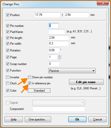
Now click [SHIFT] + M11 (or just M11) upon the connection pin. The dialog "Change pins" appears:
Untick the box "Show pin number". Tick the box "Is reference-pin". Dont tick this box prior to the use of the [y] key. Otherwise you will receive the error message: "Pin already connected to a signal!".
Give a signal name to the pin by the use of the button "Edit pin name". If you prefix an exclamation mark you will make this signal name a variable and thus before any import you'll get asked which signal name you'd like to use. If you abandon the exclamation mark ther won't be a questioning prior to import. The signal name you had entered to the field in question will be directly used in the schematic.
Press OK ([Enter]-key).
Highlight the complete reference symbol again by a highlighting square.
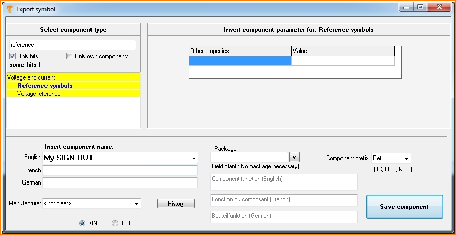
Press keyboard key [x]. The dialog "Export symbol" appears.
- From the list on the left select the component type "Reference symbols" from the "Voltage and current" group. Search e.g. by reference and tick the box "Only hits".
- In the "Insert component name" area, enter a component name in the "English" language field, for example My SIGN-OUT - just to divide it from others by the name.
- For "Manufacturer", select "not clear".
- Further properties can be optionally assigned in the middle area of the dialog.
- A package is not required, so leave this field blank.
- The entry "Ref" should appear automatically for Component prefix.
- Now press the "Save component" button.
- A package proposal is not required, so negate the question about a package for the PCB in the dialog popping up.
- The additional safety question whether the component should be a reference symbol please confirm by "Yes".
- The next dialog to edit the symbol just closed with the red X in the upper right corner.
If you press the [r] key in the schematic view, you are taken directly to the reference symbol selection. The reference symbol you have just drawn appears in the list with its name and USER flag and can instantly be imported into the schematic.


