Difference between revisions of "Pick and place"
| Line 1: | Line 1: | ||
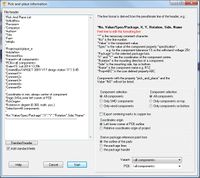
The output dialog "Pick and place" can be fond in [[Menu File]] / [[Input/Output Formats]] / [[Production]].<br> | The output dialog "Pick and place" can be fond in [[Menu File]] / [[Input/Output Formats]] / [[Production]].<br> | ||
| − | [[Image:e_PicPlaceDlg.jpg|none]] | + | [[Image:e_PicPlaceDlg.jpg|none|200px]] |
Here you can output information on automatic "pick and place" into a textfile. Coordinates are relative to the lower left corner of the PCB. If you however select "Only components on bottom", then the lower '''right''' corner is the origin. This is because you should insert the PCB bottom side top into you machine. | Here you can output information on automatic "pick and place" into a textfile. Coordinates are relative to the lower left corner of the PCB. If you however select "Only components on bottom", then the lower '''right''' corner is the origin. This is because you should insert the PCB bottom side top into you machine. | ||
Revision as of 09:38, 15 March 2013
The output dialog "Pick and place" can be fond in Menu File / Input/Output Formats / Production.
Here you can output information on automatic "pick and place" into a textfile. Coordinates are relative to the lower left corner of the PCB. If you however select "Only components on bottom", then the lower right corner is the origin. This is because you should insert the PCB bottom side top into you machine.
TARGET uses the center of each component. Therefore TARGET draws a rectangle around all centers of the components pads. The center of this rectangle gives the component coordinates. Very unsymmetric components can result in coordinates that may demand an offset in the machine's component settings.


