Pick and place
General
The output dialog "Pick and place" can be found in Menu File / Input/Output Formats / Production / Pic-And-Place automat (pic & place)...
Sometimes this output format is called Centroid.
Automatic assembly
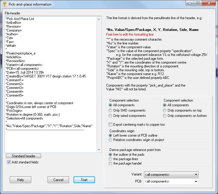
Pick and Place dialog in Menu File/Input/Output Formats/Production/Pic-And-Place automat (pic&place)...
This dialog allows the creation of data on automatic "picking and placing" into a text file. Coordinates are relative to the lower left corner of the PCB. If you select "Only components on bottom", then the lower right corner is the origin. This is because you then would insert the PCB bottom side top into your machine.
TARGET 3001! uses the coordinates of the center of each component being derived from the complete footprint image-outline.
Until V15.9.0.1 around each center of each soldering pad a rectangle was placed.
The component property "PICK_AND_PLACE" with the value "NO" ensures that the component is not output in the Pick&Place list.
Output in EXCEL format
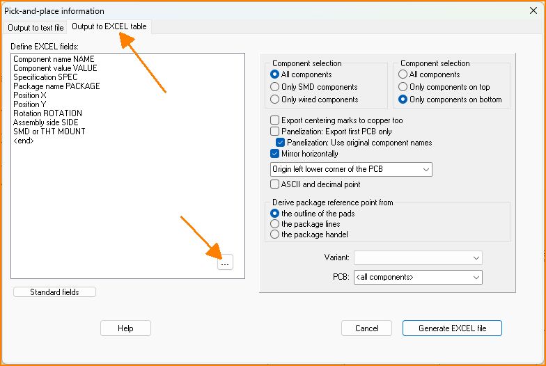
Image: Pick&Place output in Excel format (from V32)
The assembly of PCBs is enormously facilitated, because the pick-and-place operators like to process Excel tables. Microsoft Excel itself is not required as a program on the computer to generate the Excel file. Use the upper right tab. You can also add your own component properties by clicking on the button with the 3 dots.
Reel orientation
- Component properties REEL_ORIENTATION, REEL_OFFSET_X and REEL_OFFSET_Y established (Caution: The offset's unit is nm. 1 mm = 1000000)
You can add a property "REEL_ORIENTATION" to every component. The aim is to ease assembly if you know how the parts orientation on reel is:
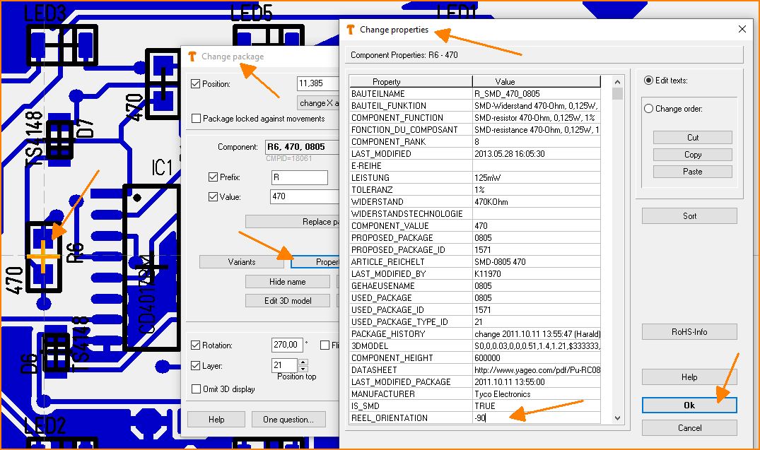
(Fig. 1: Property)
You can also select several components together with [Shift] and then press [e] for edit:
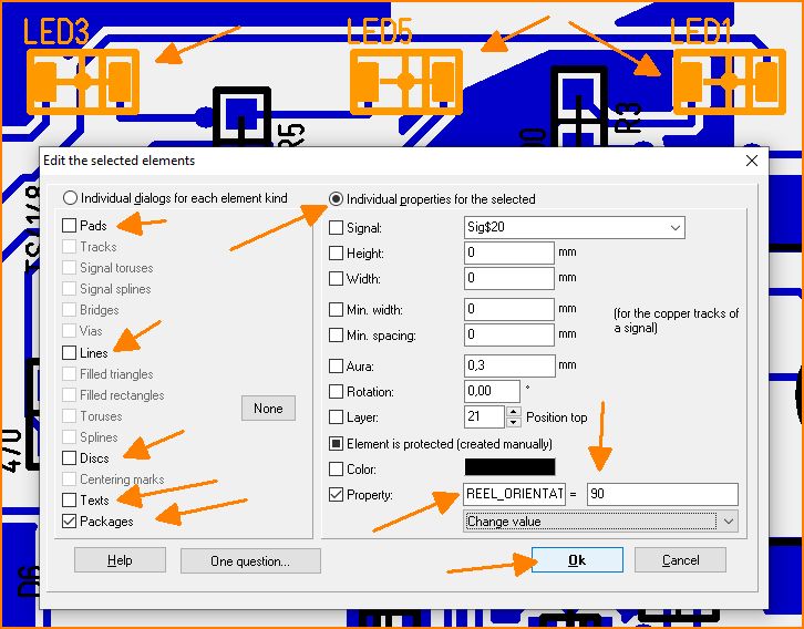
(Fig. 2: Set property for several components together)
The ideal method would be, if the components in the component database already had this property before you place them on the PCB. The value of REEL_ORIENTATION is then added to the package's orientation when when the component is output via the Pick&Place dialog.
User defined property
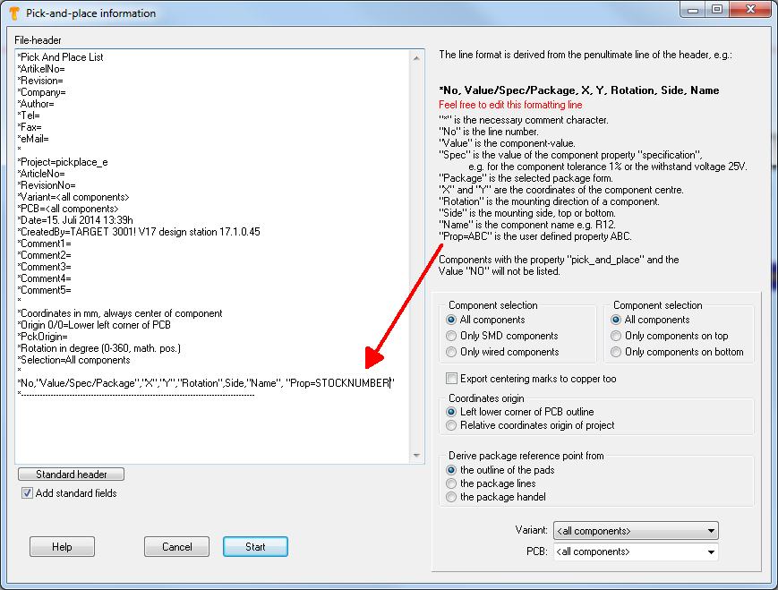
Maybe you'd like to put out a certain property of the components to the pic & place list, for example the stock number. Precondition is, that the components in question show this property and a value to this property is given. So add to the last but one line: ,"Prop=STOCKNUMBER"- important is the comma and the quotation marks. In the layout you for example have 5 components in use, furnished with individual stock numbers:
In the Pic&Place dialog it looks like that:
If you push the start button, the following entries are visible:
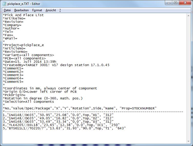
Image: The Pic&Place result
It is a simple text file, to be edited by any text editor. The desired STOCKNUMBERS see in the last column..
Declare a package with drills as SMD
Through holes or vias, or mounting holes within a SMD package make TARGET think that it would be a wired one (THT). In consequence in the pick and place list it would not appear in the row of the SMD ones which nevertheless might be wanted. In order to get that, you can add the property: "IS_SMD" and set its value "TRUE" to the properties of a part. Afterwards it can be saved to the data base. But also parts already used in a design can be furnished with this property which counts then already.
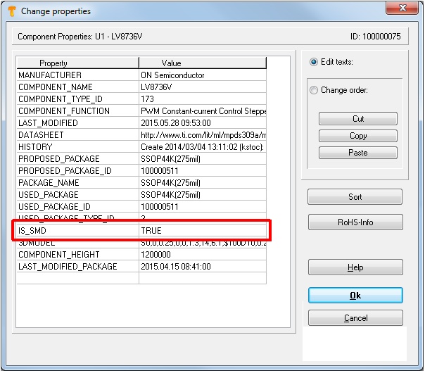
Image: A non-SMD package can be declared as such by assigning this particular property to it.


