Outline
When we talk about "outline" we mean the outer contour of the board which can achieve any shape. Sometimes the shape of a component (package) is called outline too. Then please see Edit component.
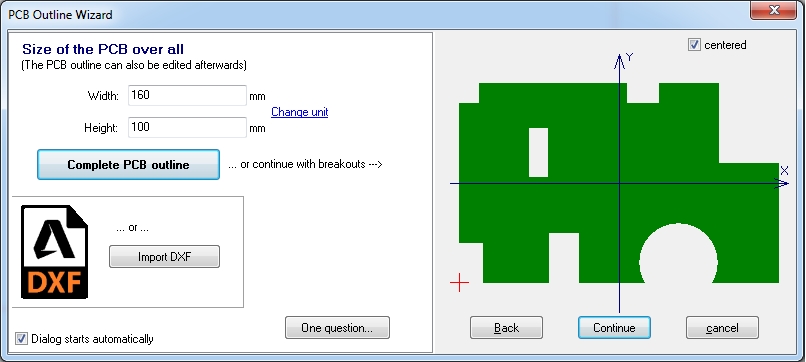
The PCB Outline Wizard in layout "Menu Actions/Automatisms and Assistants/PCB Outline Wizard" assists you step by step in creating the PCB outline. By default it is drawn upon layer 23, PCB outline. The CAM data recognize the width of the cutting tool that way, that the outer measurements of the board are middle of the outline, independently from the width of the outline in the layout. If you want to see exactly where it runs, please use the hash key (#) to get an X-ray view of the complete board where you can see the middle of the line.

Image: The PCB Outline Wizard
Pressing the button [Complete PCB outline] by default the outline is placed in the first quadrant of the drawing area (1). This means that the orgin is bottom left. Alternatively check the box "centered" (2). The board outline then will be placed centrally around the absolute zero of the drawing area (3).

Image: The PCB Outline Wizard
The PCB Outline Wizard supports you when using rectangular or circular cut-outs by pressing the "Continue" button. You also might use such inner sections, in the sense of route prohibition zones (an outline within the outline). You would simply delete them after routing.
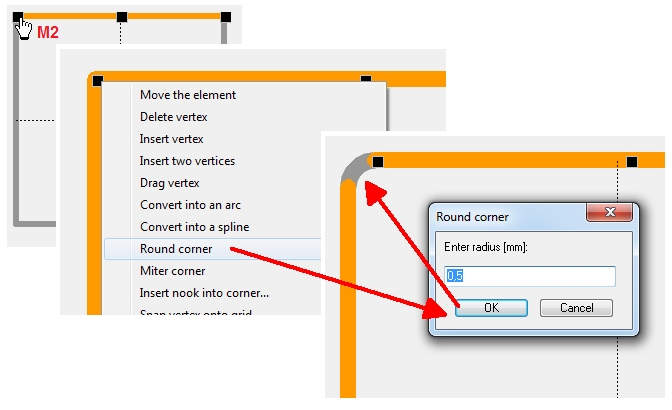
You either may draw a customized outline (having any shape, break outs or rounded corners...) on the outline layer (23=Outline). Just use the drawing functions. Choose the drawing function "Draw lines" under the pencil icon, ![]() press key [o] for "options" afterwards and set "layer = 23". Place and modify this outline the way you like. Highlight a certain part of the outline and see those black boxes at the end of the line. Hover the mouse over such a box and press M2. A context menu shows the opportunities. There you might use the option of "round or miter corners". It makes sense to play a bit with the context functions to get familiar with them. Use the "Undo" - function if needed. For bends and bows towards the inside please also note the function trim lines within the article line.
press key [o] for "options" afterwards and set "layer = 23". Place and modify this outline the way you like. Highlight a certain part of the outline and see those black boxes at the end of the line. Hover the mouse over such a box and press M2. A context menu shows the opportunities. There you might use the option of "round or miter corners". It makes sense to play a bit with the context functions to get familiar with them. Use the "Undo" - function if needed. For bends and bows towards the inside please also note the function trim lines within the article line.

Image: Any shape is thinkable. Also see Rectangle.
If you have a predefined outline in DXF format, use the DXF import. The individual steps are described in article DXF. Look there at "Import a DXF-File".
Round corners:

Image: M2 means right click. Round corner by entering the corner radius...
Please regard the function to trim lines in article line. Also the function of placing the cursor related to another object's geometry in article Coordinates might be helpful for mechanic constructing. Or in general the article Vertex, bending.
To carve the board outline or to mill the outline leaving tabs for later breakout, please look here: Engraving insulation channels/Outline

