Multisymbol
If you want to place certain pin groups of a component symbol at different places in the schematic or on different schematic pages, you can create the component symbol so that it consists of several sub-symbols (pin groups). The individual sub-symbols can - one after the other - be brought into the schematic and placed separately.
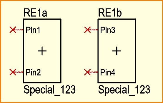
Figure: Symbol of the four pin component RE1 with two sub symbols a and b.
To make it quick: When drawing (creating) the symbol, you mark such a pin group (sub symbol) and set its own handle cross at inner position using the keyboard key [y]. Do this for all pin groups. Finally, mark everything and save it with [x].
In detail.
Go to schematic view.
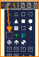
Figure: Use drawing tool to place pins for a new symbol.
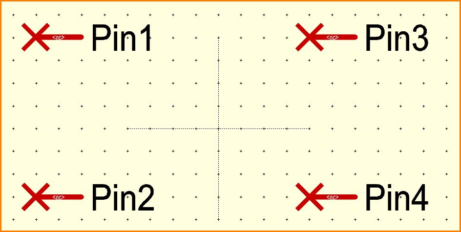
Figure: Four pins placed one after the other by click, numbers 1 to 4 are given automatically. At the shaft of the pin, where <nc> shows, later the signal name will show up, as soon as connected.
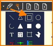
Figure: Use drawing tool to draw an "Open (unfilled) rectangle"
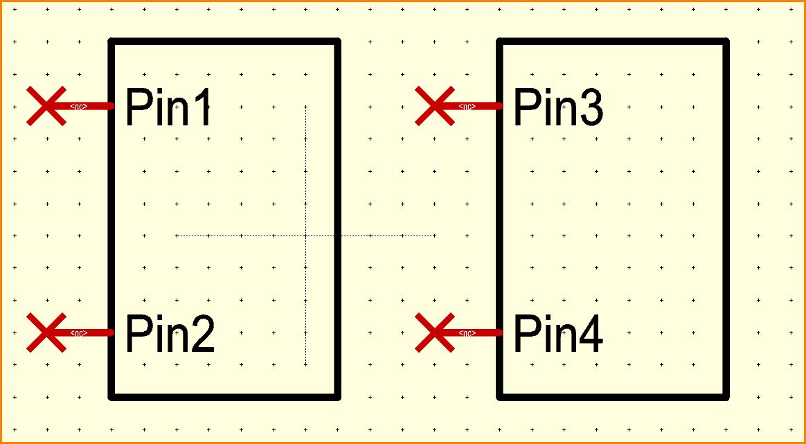
Figure: Rectangles drawn as body of the sub symbols (any other shape is possible).
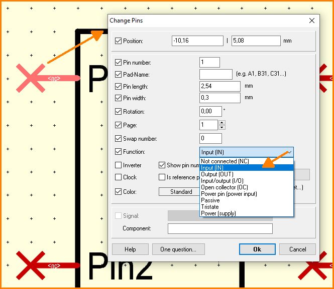
Figure: Double click each Pin and set its function.
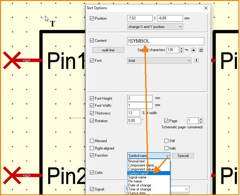
Figure: Use text tool (key ["]) and click above black frame. Select text function Symbol name.
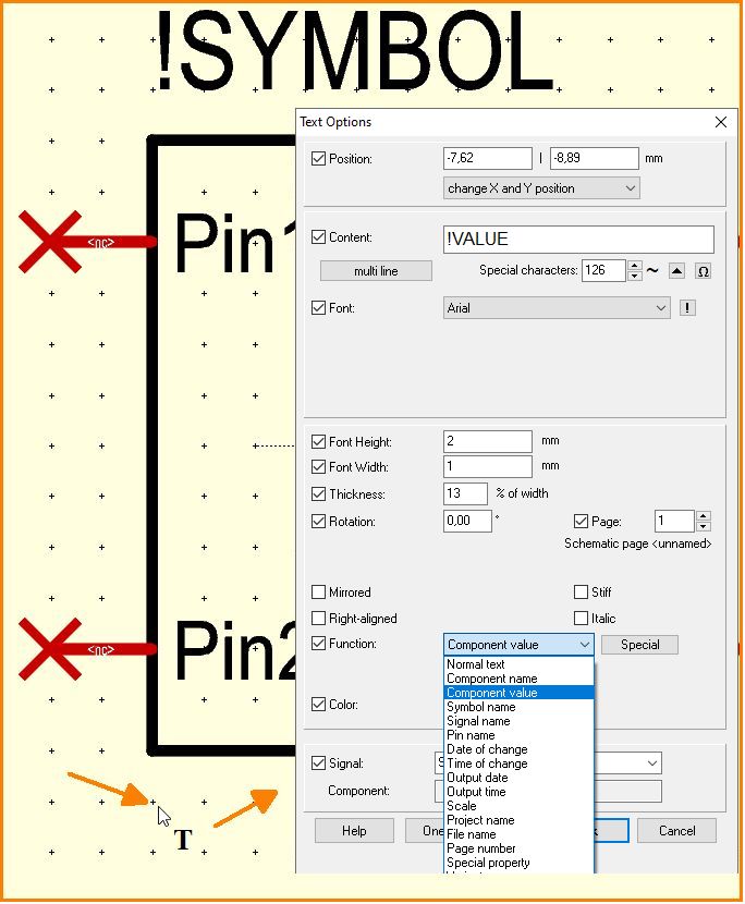
Figure: Use text tool (key ["]) and click below black frame. Select text function Component value.
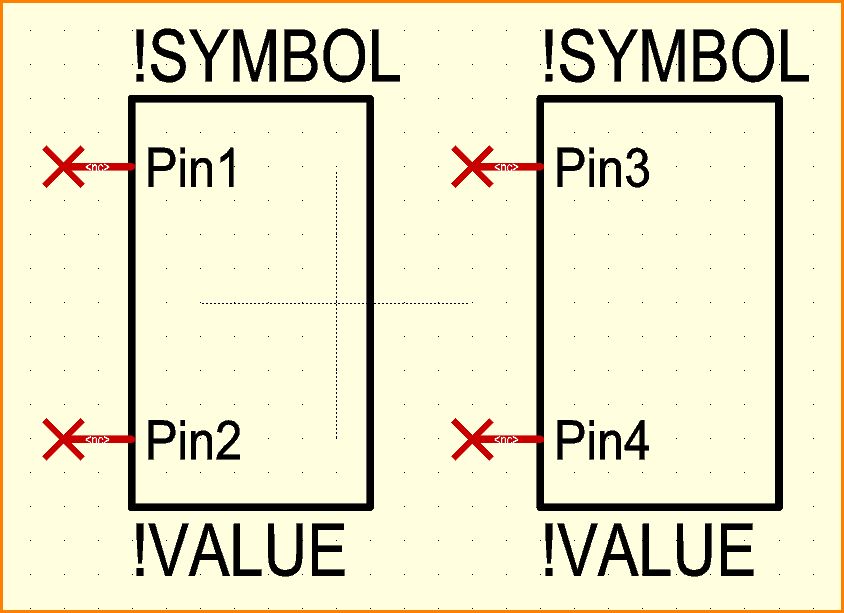
Figure: Do the same with the other sub symbol.
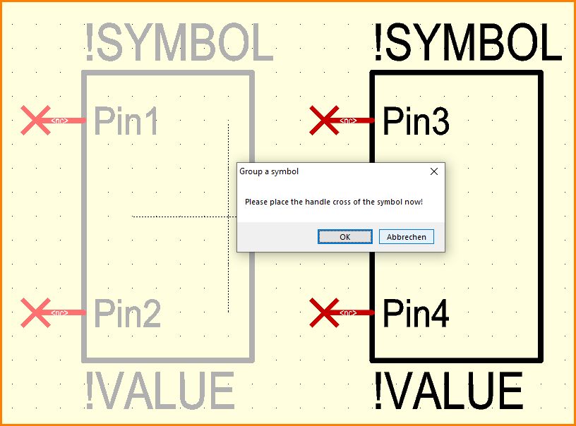
Figure: Now mark the left sub-symbol with the snap window and press the keyboard key [y]. Confirm merging as a group.
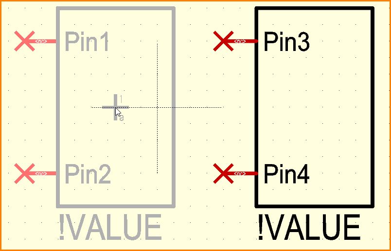
Figure: A click to the center place its handle.
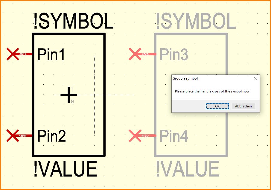
Figure: do the same to the right: Mark all elements and press key [y]. Confirm merging as a group.
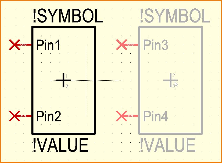
Figure: A click to the center place its handle here too.
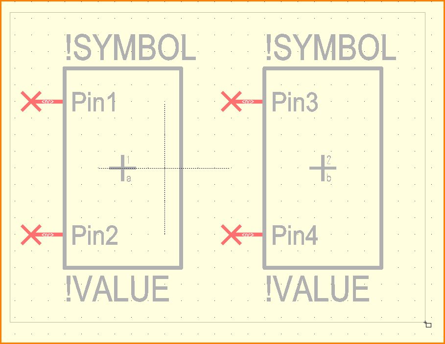
Figure: Mark all and press key [x], in order to expoet all to the component data base (= save).
![press key [x] to save all](/wiki/ibfwikien/images/8/8f/Multisymbol14_e.jpg)
Figure: Enter to the export dialog, assign an appropriate package, save. Done.

