Difference between revisions of "Module"
| Line 7: | Line 7: | ||
Let's say you'd like to group the elements in the red circle as a module named "Reset". | Let's say you'd like to group the elements in the red circle as a module named "Reset". | ||
| − | [[Image:modul1.jpg|none| | + | [[Image:modul1.jpg|none|300px]] |
Highlight all elements which shall be part of the module using '''[Shift] + [[M1]]''' subsequently. | Highlight all elements which shall be part of the module using '''[Shift] + [[M1]]''' subsequently. | ||
| − | [[Image:modul2.jpg|none| | + | [[Image:modul2.jpg|none|300px]] Now press [[M2]] on empty space. The following menu opens: |
| − | [[Image:modul3_e.jpg|none| | + | [[Image:modul3_e.jpg|none|300px]] |
Use menu entry "Group the selected elements as a module" and give an appropriate name to the module. "Reset" in our case. | Use menu entry "Group the selected elements as a module" and give an appropriate name to the module. "Reset" in our case. | ||
| − | [[Image:modul4_e.png|none| | + | [[Image:modul4_e.png|none|300px]] |
| Line 28: | Line 28: | ||
| − | [[Image:modul5_e.png|none| | + | [[Image:modul5_e.png|none|300px]] |
| Line 34: | Line 34: | ||
All elements of the module in question get highlighted. | All elements of the module in question get highlighted. | ||
| − | [[Image:modul2.jpg|none| | + | [[Image:modul2.jpg|none|300px]] |
| Line 49: | Line 49: | ||
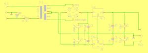
| − | [[image:netzteil_S1.jpg|none| | + | [[image:netzteil_S1.jpg|none|300px|Image 1: Power supply (schematic)]] |
'''Image 1''' shows the schematic of a symmetrical universal power supply | '''Image 1''' shows the schematic of a symmetrical universal power supply | ||
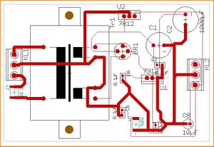
| − | [[image:netzteil_L1.jpg|none| | + | [[image:netzteil_L1.jpg|none|300px|Image 2: Power supply (layout)]] |
'''Image 2''' shows a layout of it | '''Image 2''' shows a layout of it | ||
| − | |||
| Line 60: | Line 59: | ||
| − | [[image:netzteil_S2.jpg|none| | + | [[image:netzteil_S2.jpg|none|300px|Image 3: Paste the schematic as a module]] |
Now paste the clipboard by '''[Ctrl]+[v]''' to an empty schematic page, see image 3. | Now paste the clipboard by '''[Ctrl]+[v]''' to an empty schematic page, see image 3. | ||
| − | [[image:netzteil_L2.jpg|none| | + | [[image:netzteil_L2.jpg|none|300px|Image 4: Paste the layout as a module]] |
| Line 77: | Line 76: | ||
It's possible to subsume components to a module (group of components, assembly) for a common edition. The affiliation of a component to a certain group is defined by it's property '''MODULE'''. Highlight those symbols (in the schematic) view which you'd like to group and press key '''[e]''' for '''e'''dit. The following dialog opens: | It's possible to subsume components to a module (group of components, assembly) for a common edition. The affiliation of a component to a certain group is defined by it's property '''MODULE'''. Highlight those symbols (in the schematic) view which you'd like to group and press key '''[e]''' for '''e'''dit. The following dialog opens: | ||
| − | [[Image:e_module.jpg|none| | + | [[Image:e_module.jpg|none|300px]] |
For those components highlighted we add the property '''MODULE = Power supply unit''', because we want to make them belong to the module "Power supply unit". | For those components highlighted we add the property '''MODULE = Power supply unit''', because we want to make them belong to the module "Power supply unit". | ||
| Line 83: | Line 82: | ||
Later you can use the module property of several components eg when using the [[Autoplacer|autoplacer]], intending the autoplacement of only a certain module: | Later you can use the module property of several components eg when using the [[Autoplacer|autoplacer]], intending the autoplacement of only a certain module: | ||
| − | [[Image:e_AutoplacerDLG0.jpg|none| | + | [[Image:e_AutoplacerDLG0.jpg|none|300px]] |
| Line 89: | Line 88: | ||
| − | [[Image:e_module1.jpg|none| | + | [[Image:e_module1.jpg|none|300px]] |
Revision as of 09:50, 2 December 2014
Contents
General
The module function allows to group several elements as a module. Make up your mind about a module name in order to search and select the module by this name later. A component with several gates is always made up as a module, because TARGET thinks of a module as being a unit which is placed closely together and assembled collectively on the board.
Grouping elements
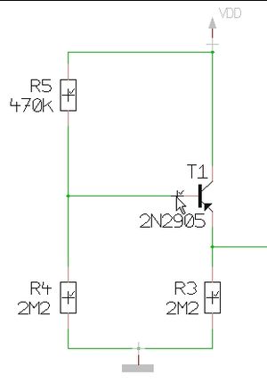
Let's say you'd like to group the elements in the red circle as a module named "Reset".
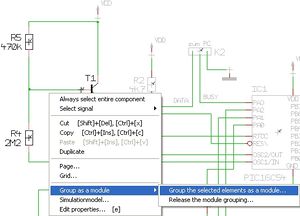
Highlight all elements which shall be part of the module using [Shift] + M1 subsequently.
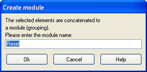
Use menu entry "Group the selected elements as a module" and give an appropriate name to the module. "Reset" in our case.
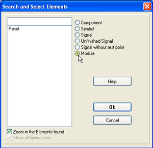
Later, when you'd like to highlight the complete module, please use the search function (the binoculars). Tick the radiobutton "Module" and choose the desired one by selecting it's name from the list.
All elements of the module in question get highlighted.
If you press this button in The pointer toolbar: ![]() you will highlight all elements of a module if you click on part of it.
you will highlight all elements of a module if you click on part of it.
Using a prepared assembly as a module
Subassemblies, which might be used in several designs can be seen as a kind of "multi element" (e.g. power supplies). So you would like to insert them as a module instead of creating them new each time. How do you do that? After having drawn a schematic and a layout of such a subassembly copy it to the clipboard and paste it to a new, empty project. Schematic first, then the layout. Save this project under a reasonable name. Later open this new project again and pick the assembly from it. Paste it to your desired design, schematic first, then the layout.
For example: A symmetrical universal power supply powersupp_univ_sym.T3001
Image 1 shows the schematic of a symmetrical universal power supply
Image 2 shows a layout of it
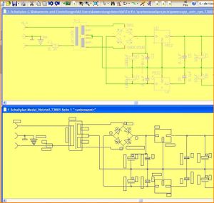
Now open an empty project and tile the window horizontally. Now take the complete schematic of the module to the clipboard. For doing so drag a Catch window over the complete figure and press [Ctrl]+[c].
Now paste the clipboard by [Ctrl]+[v] to an empty schematic page, see image 3.
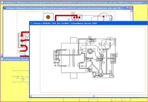
Do the same with the layout, see image 4.
Gather subassemblies of components for common edition
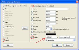
It's possible to subsume components to a module (group of components, assembly) for a common edition. The affiliation of a component to a certain group is defined by it's property MODULE. Highlight those symbols (in the schematic) view which you'd like to group and press key [e] for edit. The following dialog opens:
For those components highlighted we add the property MODULE = Power supply unit, because we want to make them belong to the module "Power supply unit".
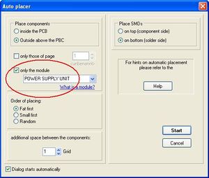
Later you can use the module property of several components eg when using the autoplacer, intending the autoplacement of only a certain module:
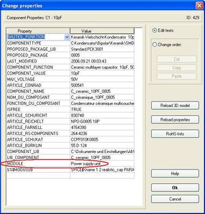
If a component belongs to a module can be figured out by it's list of properties. Click M11 on the handle of the component and click button "Properties" in the appearing "Change component" (symbol or package) dialog:


