Autoplacer
General
In respect to automized placement there are two assistants which can be activated in Layout Menu Actions:
- The Autoplacer which automatically places the package proposals of the components to the layout.
- The Alignment Assistant which arranges a bunch of identical components according to certain geometrical figures eg 20 LEDs in a half circle (see the linked article).
The autoplacer calculates immediately the shortest distance of signal tracks between the packages during the placement. A PCB-outline must be defined before launching the autoplacer. TARGET 3001! opens the layout view already showing a default outline which you can edit. The Autoplacer places packages being predefined by the schematic symbols as their corresponding package proposal. If you want to autoplace a different package, you have to change the entry in the property list of the schematic symbol (double click on its handle cross and press button "Properties" in the flashing dialog).
A resonable placement of parts is a must for every layout unless you like to create layouts having only limited extent. First focus on the question which kinds of parts need to be placed. We recommend first to place the following parts manually prior to starting the autoplacer:
- Connectors and all parts having a predifined position in order to fulfill mechanical demands (transformers, potentiometers)
- Big parts and those ones having lots of pins (ICs). In other words those ones caring for a certain segmentation of the layout in functional blocks.
- (Oscillators, Crystals) and their capacitors needing to get placed very close to the processor.
- Blocking capacitors for für ICs
Now start the autoplacer in order to let it do the rest of the work. A board showing a disadvantageous component allocation is difficult to route and even might be restricted in it's functionality.
The Auto placer dialog
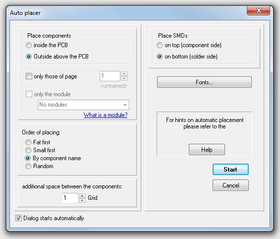
Image: The Auto placer dialog
You can activate it alternatively:
- by the tool
 under the icon
  , after you have finished the schematic and the definition of the PCB outline.
 - by menu option "Launch Autoplacer" in Menu Actions
- after pressing
 tick the box
  in Dialog:
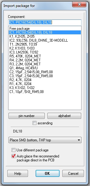
Image: While in the Import package for dialog tick the box in the last line to start the Auto placer.
Contents of the dialog
Autoplacement can happen out of the PCB outline or within the PCB outline. An autoplacement out of the PCB outline needs an active dragging of the components (M1H)into the outlined canvas later. When autoplacing within the outline a nearby placement of the components is optimized.
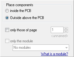
Image: The Place components section
You can autoplace certain classes of components e.g. only those of schematic page 1 or only those which belong to a certain module.
The order of placing
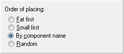
Image: The Order of placing section
Ticking the box defines placing priority...
Additional space between the components

Image: The additional space section
Entering a Zero means narrow optimized placement. Any higher digit gives additional space in entered grid units.
Placement of SMD device

Image: The Place SMDs section
Normally any component (wired or SMD) comes in from the library for mounting upon the assembly side of the PCB (layer 16, Copper top, respectively layer 21, Position top). When autoplacing SMD device, you can define their destination here.
Determine fonts
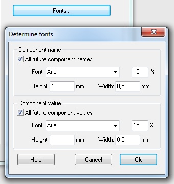
Image: The Fonts... button refers to the fonts of Component name and -value
Please Note:
- Before launching the placer, you must define a board outline (normally an open rectangle on layer 23).
- The autoplacer uses the package proposals of the schematic symbols. For using different packages, please change this value first.
- TARGET 3001! tries to rotate the packages in 90° steps. You can restrict the rotation to "No rotation" or "180° only". Enter the following line into the component properties: "AUTOPLACER_ROTATION=360" this equals "no rotation". Or choose "AUTOPLACER_ROTATION=180". This equals a rotation in 180° steps.
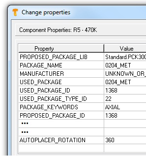
Image: Double click M2 on the handle cross of the symbol in the schematic and click on the button "Properties" to open this dialog.
- 360 means: The package mustn't be rotated when auto placed. On the PCB it will appear the way it once had been saved to the data base.
- 180 means: The package is only to be rotated in 180° steps. On the PCB it will appear either the way it once had been saved to the data base or rotated by 180°.

