Meander a track
To design a track segment in meander style means bringing it into length within a certain distance by adding a "drapery".

Image: A track having a length of 3.81 mm. We want to fold it up to a length of 15mm within its distance given by meandering it.
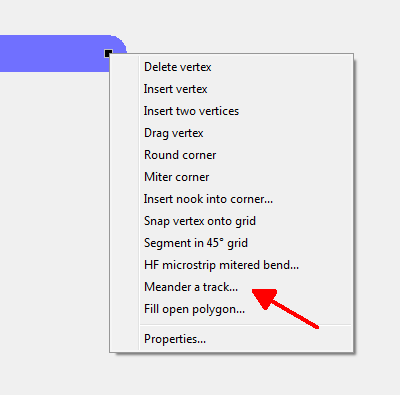
Image: Option "Meander a track" in context menu. Click M2 on a black touchpad at the end of a highlighted track segment.
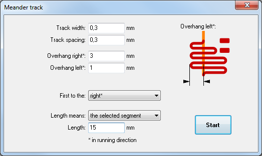
Image: The dialog "Meander track".
Overhangs to the left and the right can vary. Right and left are ment according to the running direction of the signal hit (depends on the black end box hit). The definition of length, here: 15 mm, can apply to the complete signal or only to the highlighted track segment. In our example it is only one segment. The result might look that way:
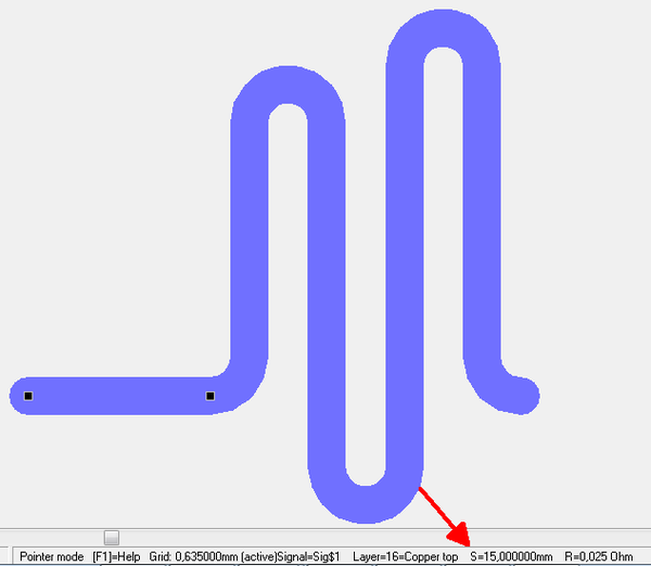
Image: Meandering track segment according to the settings in the dialog.
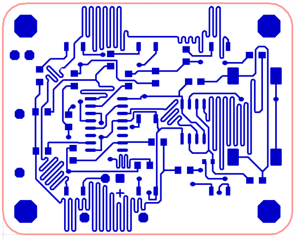
Image: The function "Meander a track" used in a project as an example
The function recognizes the distance to other signal-leading elements according to the settings in the dialog.
Since version V20.5.0.73 differential pairs can also be meandered to gain certen lenghts:
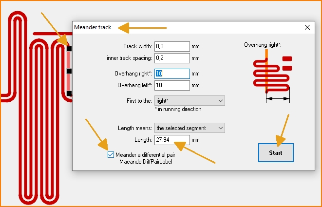
Image: Meander with Differential Pairs
Meander interactively
Mark a trace segment and aM2 click on a black marker box opens this function. In interactive meandering mode, the information box at the mouse pointer provides information about the reached trace length. The further you move the mouse, the more huge the meanders will be.
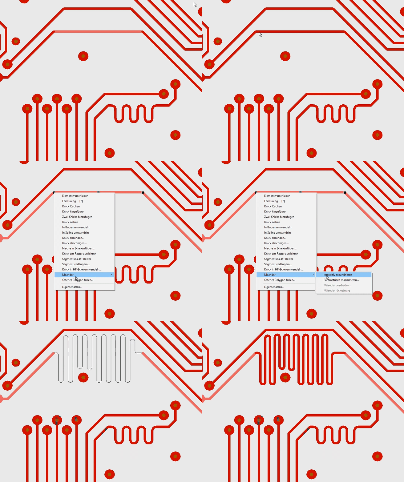
Image: Meander an existing segment interactively
With the mouse button M2 you can switch whether the meander draws its loops on both sides of the starting line or only on the side of the mouse. The mouse position also basically determines the direction in which the first loop goes. The narrowness of the loops is determined by the minimum distance in the DRC (check) and the minimum distance of the copper layer.

