Internal connections
One signal, one pin but two pads
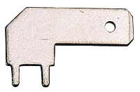
In a component several pins/pads might internally be connected in order to have electrical load capacity. They might be used like a brigde. For example in a connector one terminal can be connected to two or even more pads:
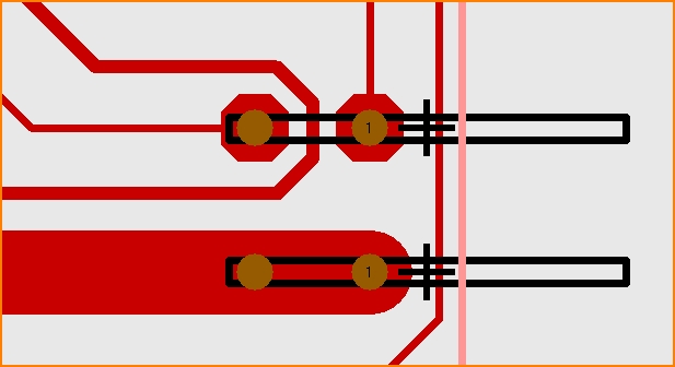
Both connections are needed to give reasonable mechanical stability. If the current load is low both connections can have separate pads. So the internal connection might be used like a bridge. Route close to one of the pads and continue routing with the other. The gap in between can be used routing through to it. But if the current load is high it might be necessary to connect both pins by a current leading piece of track. Electrically it can be sufficient to connect only one pad.
For the fact that the decision for the load capacity in most cases is not made by the designer of the part, the user of this part needs to confirm the connection. In the layout just draw two normal pads not touching each other. In the schematic create two pins as well but place them exactly superposed to each other:
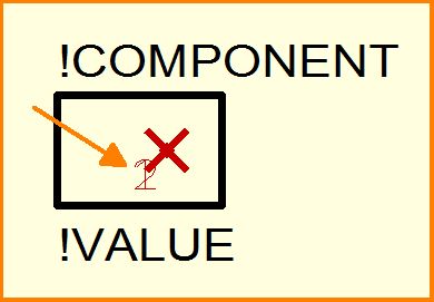
During the drawing of this symbol two pins showing the length of zero have been used. The pin names have been deleted. If several poles of the same signal in a package are wanted, several connections need to be placed superposed to each other in the symbol: 1+2, 3+4, 5+6 ...
The pin numbers 1+2 are automatically displayed side by side later:
If more than 2 pins represent one pole in a connector then the pins are combined as three: 1+2+3, 4+5+6, ... Such a combination in TARGET is called "cluster".
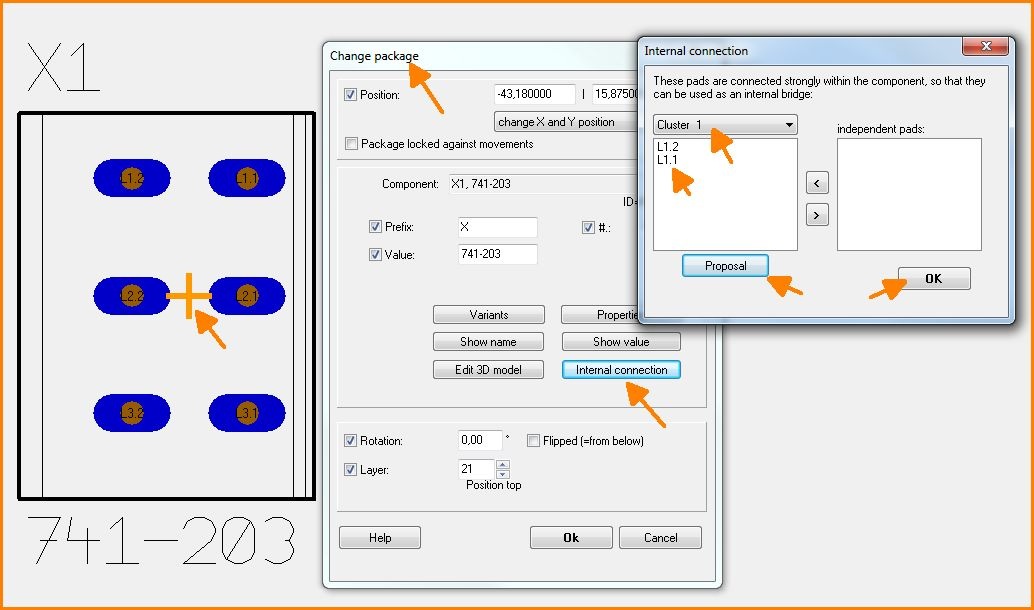
In a package being already placed to the layout please click M11 upon its handle cross. Use button [Internal connection] while the dialog "Change packages" flashes. Now the pins belonging to each other can be combined to clusters. If the pins in the schematic already are superposed to each other correctly then just confirm the proposal. In consequence TARGET combines all clusters automatically.
Important note: All pads need to be connected in this case.
Other CAD systems (e.g. Eagle) require the decision whether pins are internally connected already when drawing the part. The properties "all" and "any" are used in a "Connect" context. "all" for: all pins need to be connected, "any" for: it is sufficient to connect any pin. This may lead to problems later because the designer of the part can not know, how heavy the electrical load later will be. A push button with one pin and a 2x2 connection in a motor control sure won't lead the complete motor current through its small package just only because 2 pins are joint together to GND:
Drawing a part with internal connections
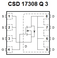
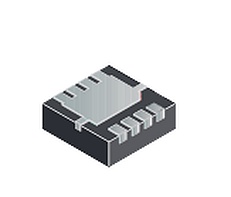
We look for example at a power mosfet CSD 1730 8Q3 from Texas Instruments that "has been designed to minimize losses in power conversion applications and optimized for 5V gate drive applications" Data sheet
The symbol shows the source connections 1, 2 and 3 (left hand side) are linked together as well as the drain connections 5, 6, 7 and 8. Only the gate terminal 4 is separate. The task is to make three from eight! because the landpattern has eight contacts and needs to come to terms with only three signals without grouching about missing connections.
Linking (concatenating) of pins in a TARGET 3001! schematic symbol is reached by superposing them.
So draw in TARGET 3001! a symbol with eight pins and and move pins two and three over pin number one. Do the same with pins number six seven and eight, superpose them over pin five. That's the way it looks at the end:
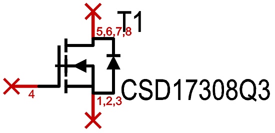
Image: Symbol of the power mosfet with internal connections drawn in TARGET 3001!
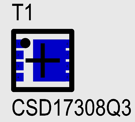
Image: Top view of the landpattern how it performs in TARGET 3001!. Eight contacts of the package SON3.3mm X 3.3mm want to get routed and soldered.


