Gridded groundplane
See also Article Groundplane
Groundplane as grid
If copper surfaces are arranged asymmetrically, thermal effects (twists and bows) can occur during the production process. It is recommended to generate ground planes as a grid (exception: high-frequency designs).
Find it in TARGET 3001! by the icons ![]() and
and ![]() or in Layoutmenu Actions / Generate Ground Plane.
or in Layoutmenu Actions / Generate Ground Plane.
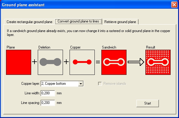
This can be done by the second tab of the "Groundplane Assistant" dialog:

Image: You should convert a groundplane to lines. If you leave space between the lines, a grid will arise. If you set the spacings between the lines zero, the plane will be solid. But anyway you should convert the plane to lines (at the end of the design process).
Using this function should be the very last step during the layout process because deleting the GND-signal from Layer 2=copper bottom, will delete the grid as well as the routed GND-signal. Also the "Check Project" Function will not work because TARGET 3001! needs to check all points of the grid against the minimum spacing set. This will take a huge calculating effort and thus take too much time.
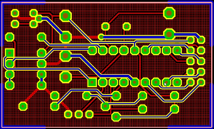
After using this function the Layout as above may look like this:

Deleting a gridded groundplane
For deletion of the gridded groundplane please use section 3 of the groundplane assistant: "Retrieve ground plane" which will create the solid status again.

