Edit elements
Any drawn element can easily be edited by a doubleclick (M11) upon it when in pointer mode. An individual dialog will open.
Alternatively you can highlight it by M1 and pressing [E] afterwards.
Alternatively you can push button ![]() beneath button
beneath button ![]()
There might arise the question of hitting it properly. Please have a look at the extension of the pointer tool: ![]()
![]() If this button is pushed, an element (component) is highlighted as a whole if exactly the handle cross is hit.
If this button is pushed, an element (component) is highlighted as a whole if exactly the handle cross is hit.
![]() If this button is pushed, an element (component) is highlighted as a whole if any element of it is hit. For most applications this button should be released.
If this button is pushed, an element (component) is highlighted as a whole if any element of it is hit. For most applications this button should be released.
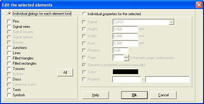
You can also highlight a region by dragging a catching window over it and thus highlihgt a multitude of elements. After pressing [E] you will get the following dialog:

Left side of the dialog: Click the radio button above left. Every element kind you have used in your project can be edited, others are idle. You will get edition dialogs for each of the selected element types. Check one (tick the radio button) and press [Return] or click M1 on [OK].
You may edit only one element kind for the entire project or parts of it using this dialog. For example you wish to widen the diameter of all drillholes from 0,800mm to 0,900mm. Catch in Layout view the whole layout M1H. Press key [E] for edit. The above dialog appears. Check the radio button on the left besides the caption "Individual dialogs for any element kind" . Now check "Pads"and press either [RETURN] or M1 upon [OK]. The dialog for "Pads" opens. Check "Drill hole" and set its value to the desired width. Enter with [OK]. Now click M11 upon a pad in the layout and see in the appearing dialog whether the adjustment is correctly done. If you wish to adjust only few drill holes, please highlight them individually by ![]() +M1 and act the same.
+M1 and act the same.
Individual properties of the selected:
Right side of the dialog: Set the same properties to different element types in this dialog.
Caution: If you change to this right side, all element types on the left will get checked, even if you manually unchecked some previously!
Example: Aura in Ground Planes:
If you wish to delete the aura from a signal, (for example you set the aura of the signal GND to zero for to connect it to the ground plane), you should leave the aura at pads and vias for three reasons:
- First: they are connected by the GND tracks anyway.
- Second: pads get hot easier for soldering.
- Third: soldering pads can not have different auras on several layers. There is danger of generating shortcuts for instance between the layers GND and VCC.
Another example: You want to move a complete schematic from page 1 to page 7:
Highlight the complete page 1 by the use of a catching window.
Press [E] to get the above dialog.
Tick "Individual properties for the selected" in menu Edit.
Tick "Layer" and enter 7 as schematic page.
Click [Ok].
Click "Go to page" in menu "View" and select page 7.

