Difference between revisions of "Drilling Plan with Pictograms"
| (4 intermediate revisions by the same user not shown) | |||
| Line 1: | Line 1: | ||
| − | [[Menu File]] / [[Input/Output Formats]] / [[Production]] / "Drilling Plan with Pictograms" | + | [[Menu File]] / [[Input/Output Formats]] / [[Production]] / "Drilling Plan with Pictograms"<br><br> |
| − | Here please create the pictograms of the drill plan. TARGET 3001! uses 20 different pictograms (figures) for 20 different drill hole diameters. Also, an ASCII-text-file with information regarding the assignment of the pictograms to the individual drill hole diameters is created. For example:<br><br><br> | + | Here please create the pictograms of the drill plan. TARGET 3001! uses 20 different pictograms (figures) for 20 different drill hole diameters. Also, an ASCII-text-file with information regarding the assignment of the pictograms to the individual drill hole diameters is created. For example:<br><br> |
| + | |||
| + | [[Image:Drillpictlegend_e.jpg|none]]Image: The section to the right represents the window of a separate text file<br><br> | ||
| + | |||
| + | The creation of graphical pictograms is used to control individual drill hole diameters on a non-automatic drilling (manual drilling). The size of the pictograms can be edited in the "Settings/Settings/Options" dialog:<br><br> | ||
| + | |||
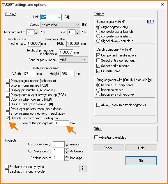
| + | [[Image:Pict_plan1_e.jpg|none]]Image: Set the dimensions of the pictograms. Or untick the box to delete the pictograms at all.<br><br> | ||
| + | |||
| + | You should create an output of the drill holes as pictogram shortly after you entered anything to the layout. The legend information does not refresh in real time. So if you make changes, please generate the drilling plan new.<br><br> | ||
| + | |||
| + | Drillholes not being plated through are indicated by an outer circle, see legend:<br><br> | ||
| + | |||
| + | [[Image:bohrplan_ndk_e.jpg|none]]Image: Indication of drills not plated through. | ||
| + | |||
| + | <br><br> | ||
| − | |||
| − | |||
[[category:Production]] | [[category:Production]] | ||
[[de:Piktogramme des Bohrplans]] | [[de:Piktogramme des Bohrplans]] | ||
[[fr:Ecrire un fichier descriptif du plan de perçage]] | [[fr:Ecrire un fichier descriptif du plan de perçage]] | ||
Latest revision as of 11:25, 16 June 2021
Menu File / Input/Output Formats / Production / "Drilling Plan with Pictograms"
Here please create the pictograms of the drill plan. TARGET 3001! uses 20 different pictograms (figures) for 20 different drill hole diameters. Also, an ASCII-text-file with information regarding the assignment of the pictograms to the individual drill hole diameters is created. For example:
The creation of graphical pictograms is used to control individual drill hole diameters on a non-automatic drilling (manual drilling). The size of the pictograms can be edited in the "Settings/Settings/Options" dialog:
You should create an output of the drill holes as pictogram shortly after you entered anything to the layout. The legend information does not refresh in real time. So if you make changes, please generate the drilling plan new.
Drillholes not being plated through are indicated by an outer circle, see legend:


