Star shaped ground: Difference between revisions
No edit summary |
(No difference)
|
Revision as of 12:22, 6 February 2012
In audio and analog circuits different ground potentials often are linked at a certain junction. A "star shaped ground" emerges.
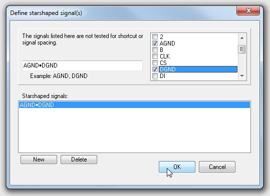
In TARGET 3001! a star shaped ground is created by simple connection of two or more signal tracks having different GND potentials/signals. To avoid a "spacing violation" alert (short circuit) when using the Check project function in TARGET 3001! you need to define the signals which shall be united prior to the check. Use option "Actions/Ground planes/Generate Star Ground" to designate those signals whose linkage shall be tolerated by TARGET 3001!:

Image 1: Dialog: Starshaped Signal(s)

Image 2: Star ground in the schematic
You may manually place such a green junction point with key [.] (= period) if you want to. And you can place such a ground symbol for clarification.

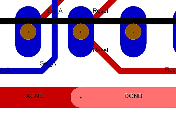
Image 3: Star ground in the layout
The feature allows to connect two signals manually. The big green junction point is just a bigger normal junction point, either of GND, AGND or DGND. The ground symbol is just a normal GND reference symbol. The autorouters ignore this all. You have to make the junction in PCB manually. Whether a connection e.g. between AGND and DGND really is created somewhere at all currently can not be checked automatically by TARGET 3001! This will stay your work...
(valid by Oct. 2009).
.

